Induction-type position measuring apparatus

a position measuring and induction-type technology, applied in the direction of electrical/magnetic position measurement, instruments, and converting sensor output electrical/magnetically, etc., can solve the problems of significant measurement errors and offset values experiencing non-negligible variation amoun

Inactive Publication Date: 2001-09-13
MITUTOYO CORP
View PDF0 Cites 32 Cited by
  • Summary
  • Abstract
  • Description
  • Claims
  • Application Information

AI Technical Summary

Problems solved by technology

These offset components can badly behave to cause significant measurement errors in cases where high-precision position detection is performed by dividing a wavelength of the scale into portions.
This approach, however, suffers from difficulty in offset removal due to the fact that offset components are significantly affectable from to the alignment accuracy of the drive and detector coils along with uniformity of materials employed therefor, resulting in the offset value experiencing non-negligible amount of variations among individual products.

Method used


Image

  • Induction-type position measuring apparatus
  • Induction-type position measuring apparatus
  • Induction-type position measuring apparatus

Examples


Embodiment Construction

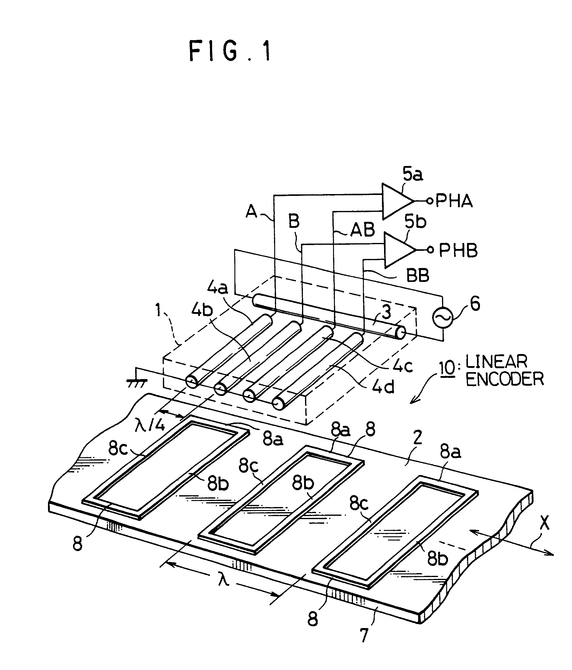
[0039] Referring now to FIG. 1, there is illustrated in perspective view a principal configuration of an electromagnetic linear encoder 10 in accordance with one embodiment incorporating the first principle of the invention. As shown herein, the encoder 10 includes in combination a sensor 1 (as a first member), and a scale 2 (as a second member). The sensor 1 and scale 2 are disposed opposing each other with a predetermined distance or gap defined between them. The scale 2 is relatively movable reciprocally along a preset measurement axis X, which is set in the longitudinal direction of the scale 2. The sensor 1 includes a drive wire 3 having a preselected length, which extends in the measurement axis X. The sensor 1 also includes parallel spaced-apart detection wires 4 that lie perpendicular to the drive wire 3 in the same plane. These wires act as detection wires, and are illustratively formed from four wires 4a-4d as one unitary group or set. The layout interval or pitch between ...


PUM

PropertyMeasurementUnit
frequencyaaaaaaaaaa
magnetic fieldaaaaaaaaaa
conductiveaaaaaaaaaa

Abstract

An inductive linear encoder (10) has a position sensor (1) and scale (2) which are movably disposed relative to each other. The sensor (1) is with a drive wire (3) to which an alternating current is supplied, and one set of detection wires (4a-4d) at right angles to the drive wire (3) in the same plane. The scale (2) is configured including an elongate substrate (7) having its surface on which a series combination of conductive closed loop patterns (8) are periodically arranged at equal intervals. These conductive closed loop (8) are linearly laid out on the substrate (7) in the relative movement direction. Each loop (8) consists essentially of a reception conductor segment (8a) and signal transmit conductor segments (8b, 8c) integral with the former (8a). The receive conductor segment (8a) is responsible for generation of an induced current due to a first variable magnetic field creatable from the drive coil (3). The transmit conductor segments (8b, 8c) are to create second variable magnetic fields that are opposite in polarity to each other and are perpendicular to the first magnetic field. Creation of such second magnetic fields results in flow of an induced current in the detector wire (4) of sensor (1), which in turn acts as a position detection output current.

Description

[0001] 1. Field of the Invention[0002] The present invention relates to an induction-type position measuring apparatus for performing position measurements based on electromagnetic coupling principles.[0003] 2. Description of the Related Art[0004] One prior known magnetic encoder employing transformers is configured including a displacement sensor and a scale structure operatively associated therewith. The displacement sensor typically has two coils: a primary coil (i.e. drive coil), and a secondary coil (detection coil). The scale is placed adjacent to the sensor and is movable relative thereto. The scale is responsible during movement for modulating the magnetic flux as generated from the drive coil. Upon activation of the drive coil by supplying an alternating drive current thereto, variable magnetic flux might take place, which is then modulated by the scale resulting in coupling with the detection coil. This magnetic coupling causes induction of a corresponding voltage at the d...

Claims


Application Information

Patent Timeline
Patent Type & Authority Applications(United States)
IPC IPC(8): G01B7/00G01D5/20G01D5/245
CPCG01B7/003G01D5/2086G01D5/2093
Inventor MIYATA, TOSHIHARU
Owner MITUTOYO CORP
Why Eureka
Try Eureka