Light emitting device and production process thereof

Inactive Publication Date: 2001-09-13
PIONEER CORP
View PDF0 Cites 4 Cited by
  • Summary
  • Abstract
  • Description
  • Claims
  • Application Information

AI Technical Summary

Benefits of technology

0010] According to the invention, since the light emitting layers are formed by a thermal transfer or sublimation method, the light emitting layers can be formed in a fixed form irrespective of the kind of

Problems solved by technology

However, when a polymer type organic EL light emitting material is used, a vacuum deposition method cannot be used as a method of forming the film of the light emitting layer because the polymer type organic EL light emitting material is not deposited by heating but decomposed.
Although a solution

Method used


Image

  • Light emitting device and production process thereof
  • Light emitting device and production process thereof
  • Light emitting device and production process thereof

Examples


second embodiment

[0052] The second embodiment

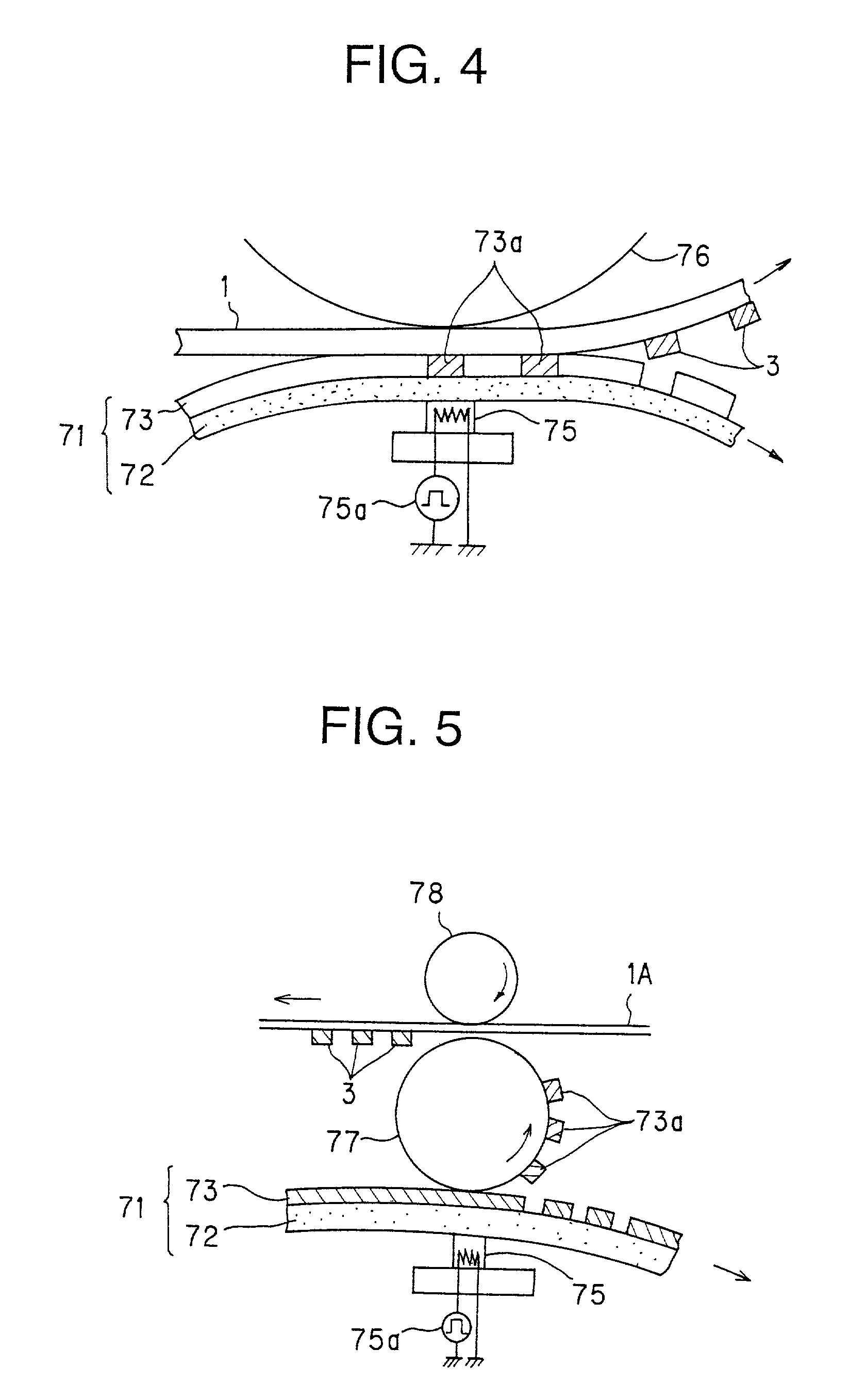
[0053] The second embodiment in which the production method of the light emitting device of the present invention is applied to the electroluminescence panel is illustrated referring to FIG. 4 below.

[0054] In the second embodiment, the light emitting layers 5R, 5G, 5B are formed using the a thermal transfer or sublimation method. FIG. 4 is a drawing showing the production method of the light emitting layer 5R. As shown in FIG. 4, a ribbon 71 is composed of a base film 72 and a transfer layer 73 which is coated on the surfaces of the base film 72 and supports a light emitting material. The transfer layer 73 is transferred on the substrate 1 by conveying the substrate 1 on which the transparent electrodes 2 are formed and the ribbon 71 between a thermal head 75 and a platen roll 76, pressuring them, and adding heat from the thermal head 75 to the ribbon 71 at a fixed timing, and the light emitting layer 5R is formed.

[0055] The thermal head 75 is provided wi...

third embodiment

[0066] The third embodiment

[0067] The third embodiment in which the production method of the light emitting device of the present invention was applied to the electroluminescence panel is illustrated below referring to FIG. 5.

[0068] As shown in FIG. 5, the ribbon 71 and the thermal head 75 being similar as in the second embodiment are used, but the transfer layer 73 of the ribbon 71 is not directly transferred on the substrate, and transferred on an intermediate transfer roll 77 having elasticity. The substrate 1A is conveyed while being sandwiched between the intermediate transfer roll 77 and the roll 78, and the fixed region 73a of the transfer layer 73 transferred on the intermediate transfer roll 77 is transferred again on the substrate 1A.

[0069] Thus, in the third embodiment, since the transfer layer 73 supporting the light emitting material is transferred on the substrate 1A through the intermediate roll 77, the transfer layer 73 can be transferred even if the substrate 1A has...


PUM

PropertyMeasurementUnit
Electric fieldaaaaaaaaaa

Abstract

A light emitting device capable of easily forming a fixed shape light emitting layer irrespective of the kind of light emitting materials is provided. The light emitting device includes a process of forming light emitting layers 5R, 5G, 5B by electrophotography, in the production method of a light emitting device in which the light emitting layers are composed of a material containing a polymer.

Description

[0001] 1. Field of the Invention[0002] The present invention relates to a production method of an electroluminescence light emitting device and the like, and specifically, relates to a production method of a light emitting device in case of using a material containing a polymer for a light emitting material.[0003] 2. Description of the Related Art[0004] An organic EL (electroluminescence) light emitting material is largely divided into a low molecular weight type material practically used at present and a polymer type material which is promising in future development. Among these, when the low molecular weight type material is used, the film forming of a light emitting layer is usually carried out by a vacuum deposition method. In this case, the light emitting layer can be patterned by a method of piling up on a substrate a shadow mask in which an opening corresponding to a pixel is formed and depositing the material, therefore a fixed form corresponding to the pixel, for example, a...

Claims


Application Information

Patent Timeline
IPC IPC(8): C09K11/06G09F9/30H01L27/32H01L51/50H05B33/10H05B33/14
CPCH01L27/3211H01L27/3281H01L51/0013H01L51/0038H01L51/5012H05B33/10H05B33/145Y10S428/917H10K59/35H10K59/17H10K71/18H10K85/114H10K50/11
Inventor MIYADERA, TOSHIYUKI
Owner PIONEER CORP
Why Eureka
Try Eureka