Carbon NANO tube coating apparatus and method thereof

Inactive Publication Date: 2011-07-28
NANOBASE
View PDF5 Cites 9 Cited by
  • Summary
  • Abstract
  • Description
  • Claims
  • Application Information

AI Technical Summary

Benefits of technology

The apparatus and method for coating a carbon nano tube according to an embodiment of the present invention has an advantage of directly applying a CNT-containing gas obtained by thermal chemical vapor deposition to a film to obtain a CNT coating film with the reduced numbers of processes and high quality through improvement of an electrical property by maintenance of dispersibility and CNT length, as compared to a conventional wet process.
The apparatus and method for coating a carbon nano tube according to another embodiment of the present invention has an advantage of manufacturing a CNT coating film through only a dry process, thereby significantly reducing a required process space and lowering process costs and hence increasing product competitiveness, as compared to a wet process requiring a plurality of separate processes.
The apparatus and method for coating a carbon nano tube according to still another embodiment of the present invention has an advantage of applying a variety of forms of rollers and reactor extensions depending on the shape of roller part and the kind of desired product by combining the roller part for deposition coating and film conveying with a reactor performing thermal chemical vapor deposition, thereby decreasing costs for change of process

Problems solved by technology

Accordingly, such a general CNT coating film manufacturing method requires a number of equipments and complicated processes and has increased costs and low yield due to various management factors occurring in the course of processes.
In addition, this method requires high costs to secure a work space for each process, which results in increase of prices of CNT coating films.
Furthermore, the existing wet method requires material such as a solution for making a CNT dispersion and means such as a mechanical article for stori

Method used


Image

  • Carbon NANO tube coating apparatus and method thereof
  • Carbon NANO tube coating apparatus and method thereof
  • Carbon NANO tube coating apparatus and method thereof

Examples


Example

BEST MODE

Hereinafter, exemplary embodiments of the present invention will be described in detail with reference to the accompanying drawings.

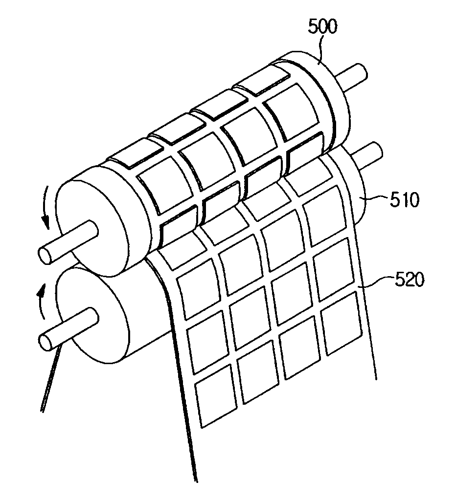
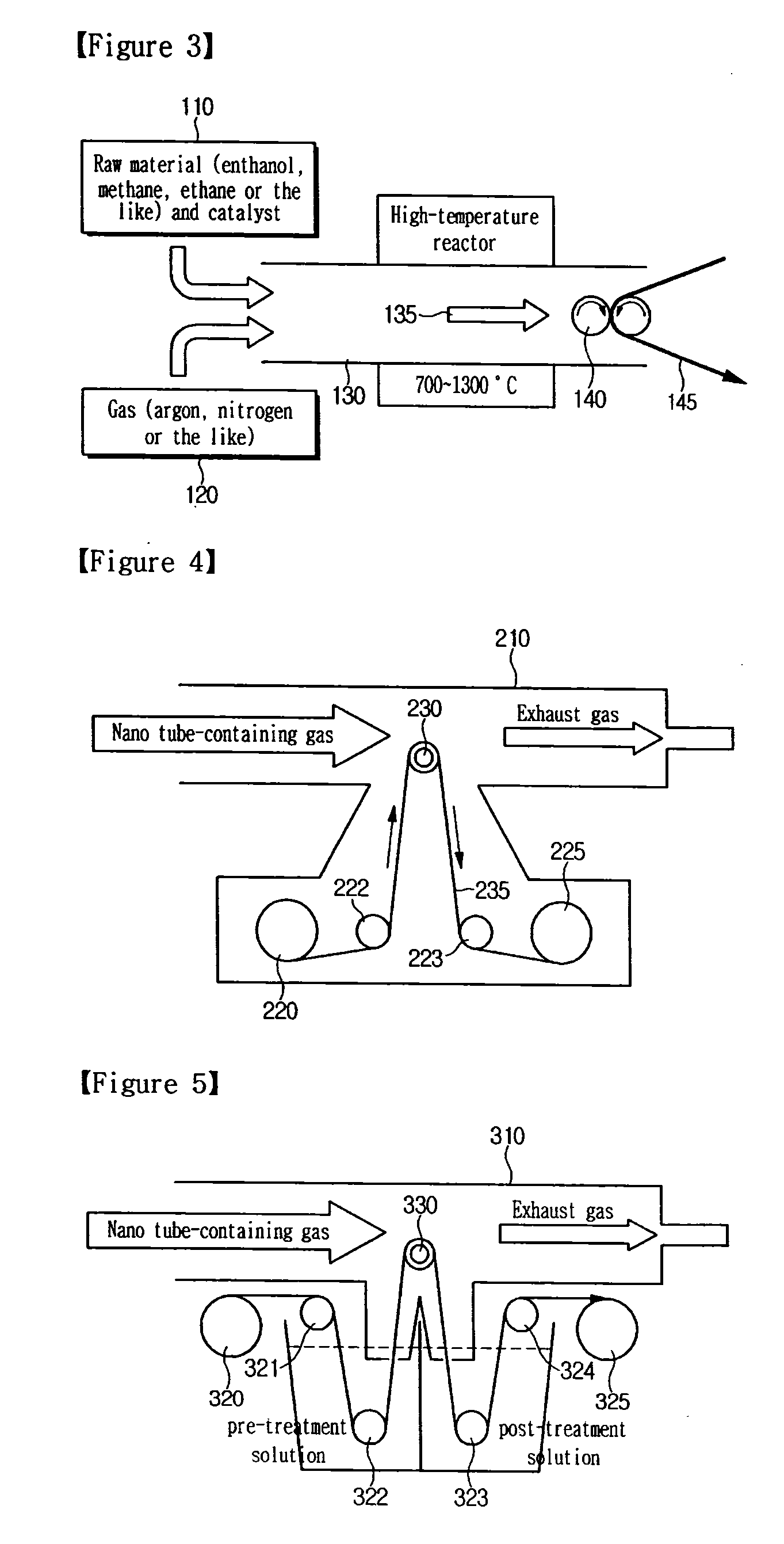
FIG. 3 is a conceptual view for explaining a configuration of an exemplary embodiment of the present invention. As shown in the FIG. 3, a structure of an exemplary embodiment of the present invention includes a high-temperature reactor 130 used for manufacture of CNT by thermal chemical vapor deposition, materials 110 and 120 provided to manufacture CNT in the high-temperature reactor 130, and a roller 140 and a film 145 as a coating and film providing unit formed in an end portion of the reactor 130.

The high-temperature reactor 130 used in the thermal chemical vapor deposition is elongated and produces a gas containing CNT. In general, the thermal vapor deposition is used to obtain a product in which CNT contained in the gas is coagulated in a bundle by cooling the end portion of the reactor. Since the coagulated bundle-like CNT will not act ...


PUM

PropertyMeasurementUnit
Temperatureaaaaaaaaaa
Lengthaaaaaaaaaa
Dispersibilityaaaaaaaaaa

Abstract

The present invention relates to an apparatus and method for coating carbon nano tubes, which is capable of coating carbon nano tubes on a film at the same time when the carbon nano tubes are produced, unlike a wet method, thereby reducing the number of processes and costs and improving performance. The apparatus and method has an advantage of directly applying a CNT-containing gas obtained by thermal chemical vapor deposition to a film to obtain a CNT coating film with the reduced numbers of processes and high quality through improvement of an electrical property by maintenance of dispersibility and CNT length, as compared to a conventional wet process.

Description

TECHNICAL FIELD The present invention relates to an apparatus and method for coating carbon nano tubes, and more particularly, to an apparatus and method for coating carbon nano tubes, which is capable of coating carbon nano tubes on a film at the same time when the carbon nano tubes are produced, unlike a wet method, thereby reducing the number of processes and costs and improving performance.BACKGROUND ART A carbon nano tubes (CNT) are allotropes of carbon with a cylindrical structure which has its diameter of 1 to 20 nm. This cylindrical structure has a unique bond arrangement of a robust and flat hexagonal plate-like film structure rolled into a spiral form to form CNT, whose edges are combined together at different points. Upper and lower portions of the hexagonal plate-like film structure are filled with free electrons which move in parallel to the structure in a discrete state.An electrical characteristic of CNT may be divided into an insulator, a semiconductor and metal base...

Claims


Application Information

Patent Timeline
IPC IPC(8): B05D5/12B05C11/00C23C16/00
CPCB82Y30/00C01B31/0273C01B31/0233B82Y40/00C01B32/162C01B32/174B82B3/00
Inventor JHUNG, JHINSUPSON, YOUNG SOOKIM, BYOUNGMIN
Owner NANOBASE
Why Eureka
Try Eureka