Production method of laminate for a battery

Active Publication Date: 2016-11-10
TOYOTA JIDOSHA KK
View PDF2 Cites 9 Cited by
  • Summary
  • Abstract
  • Description
  • Claims
  • Application Information

AI Technical Summary

Benefits of technology

[0027]The embodiments provide a production method of a laminate for a battery, in which the number of processes involved in the productio

Problems solved by technology

The thus-obtained laminate for a battery may be subject to deformation by processing such as cutting, deformation due to repetition of charge and discharge, or partial breakage by vibration, etc., during use, and the positive electrode active material layer and thereby the negative electrode active material layer could contact with each other to cause a short-ci

Method used


Image

  • Production method of laminate for a battery
  • Production method of laminate for a battery
  • Production method of laminate for a battery

Examples


Example

Example

Production of Positive Electrode Active Material Layer Formed on Release Sheet

[0132]A positive electrode mixture as the raw material of the positive electrode active material layer was put in a polypropylene (PP)-made vessel, stirred over 30 seconds by an ultrasonic dispersion apparatus (Model: UH-50, manufactured by SMT CO., LTD.), and shaken over 3 minutes by a shaker (Model: TTM-1, manufactured by Sibata Scientific Technology Ltd.) to prepare a positive electrode active material slurry.

[0133]This positive electrode active material slurry was applied on an Al foil as a release sheet by a blade method employing an applicator, and then dried on a hot plate at 100° C. over 30 minutes to obtain a positive electrode active material layer formed on a release sheet. By repeating the operation above, two positive electrode active material layers were respectively formed on a release sheet.

[0134]The configuration of the positive electrode mixture is shown below:

[0135]4.7 g of LiNi1 / ...

Example

Example 1

[0179]FIG. 4(a) is a schematic front view of part of the laminate obtained in Example 1, FIG. 4(b) is a side view of the laminate of FIG. 4(a), FIG. 4(c) is a front photograph of the A-B portion of the laminate of FIG. 4(a), and FIG. 4(d) is an SEM image when the laminate of FIG. 4(c) is viewed obliquely.

[0180]In FIGS. 4(a) and 4(b), the removing portion of the negative electrode active material layer 310 is schematically shown. It is seen from FIGS. 4(a) to 4(c) that while part of the negative electrode active material layer310 is removed, part of the solid electrolyte layer 320 remains without being removed.

[0181]It is believed that by virtue of the laser reflectance by the solid electrolyte solution being 80% or more, part of the laser is transmitted through the negative electrode active material layer and / or the direct laser are reflected from the solid electrolyte layer. This results in a high probability that breakage, etc., of part of the solid electrolyte layer is e...

Example

Example 2

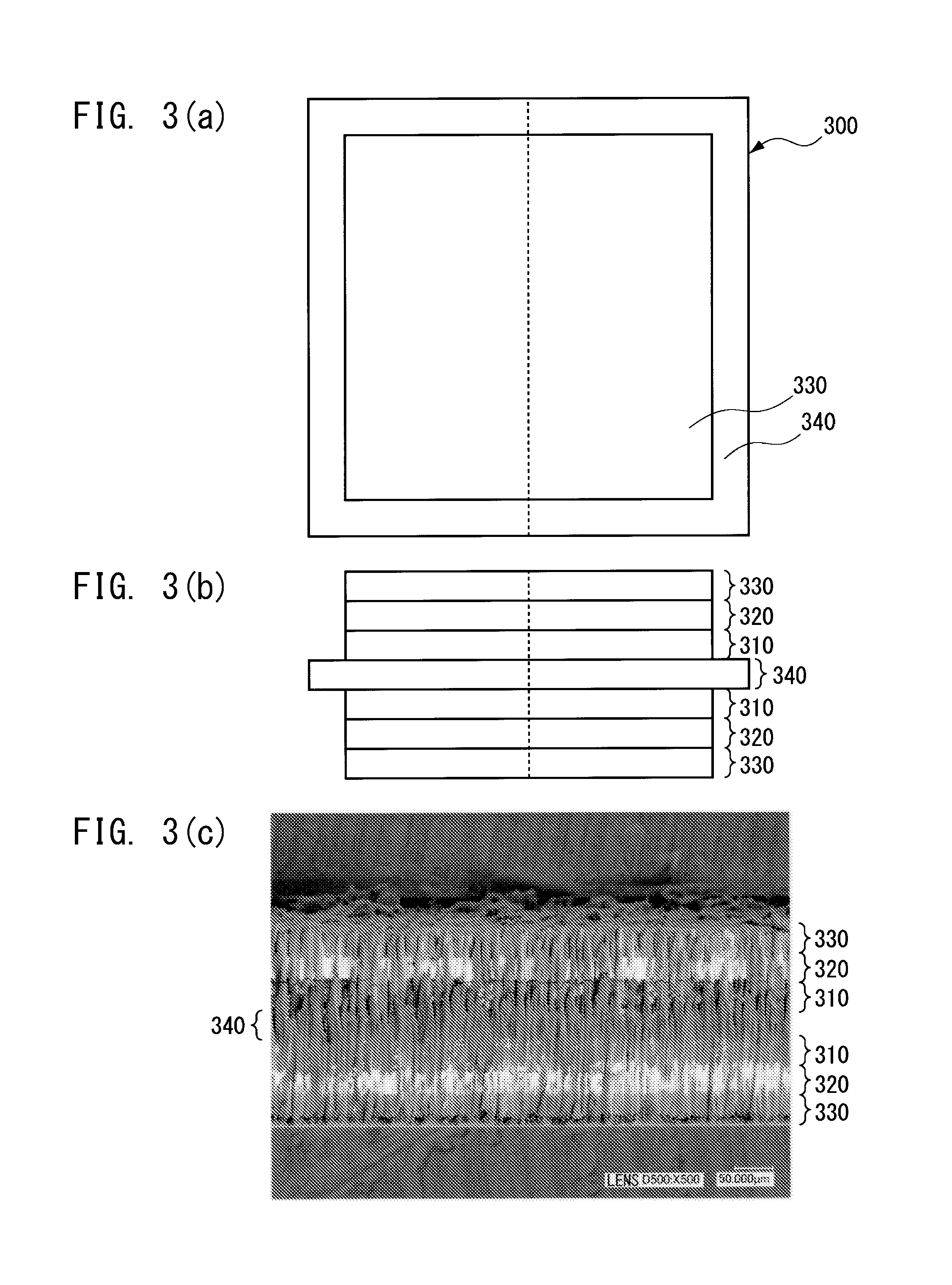
[0184]FIG. 5(a) is a schematic front view of part of Laminate 1 when Laminate 1 is irradiated with a laser having a wavelength of 1.0 μm from the positive electrode active material layer side and thereby part of the positive electrode active material layer is removed. FIG. 5(b) is a side view of FIG. 5(a) and FIG. 5(c) is a front photograph of the A-B portion of FIG. 5(a).

[0185]In FIGS. 5(a) and 5(b), the removing portion of the positive electrode active material layer 330 is schematically shown. It is seen from FIGS. 5(a) to 5(c) that while part of the positive electrode active material layer 330 is removed, part of the solid electrolyte layer 320 remains without being removed.

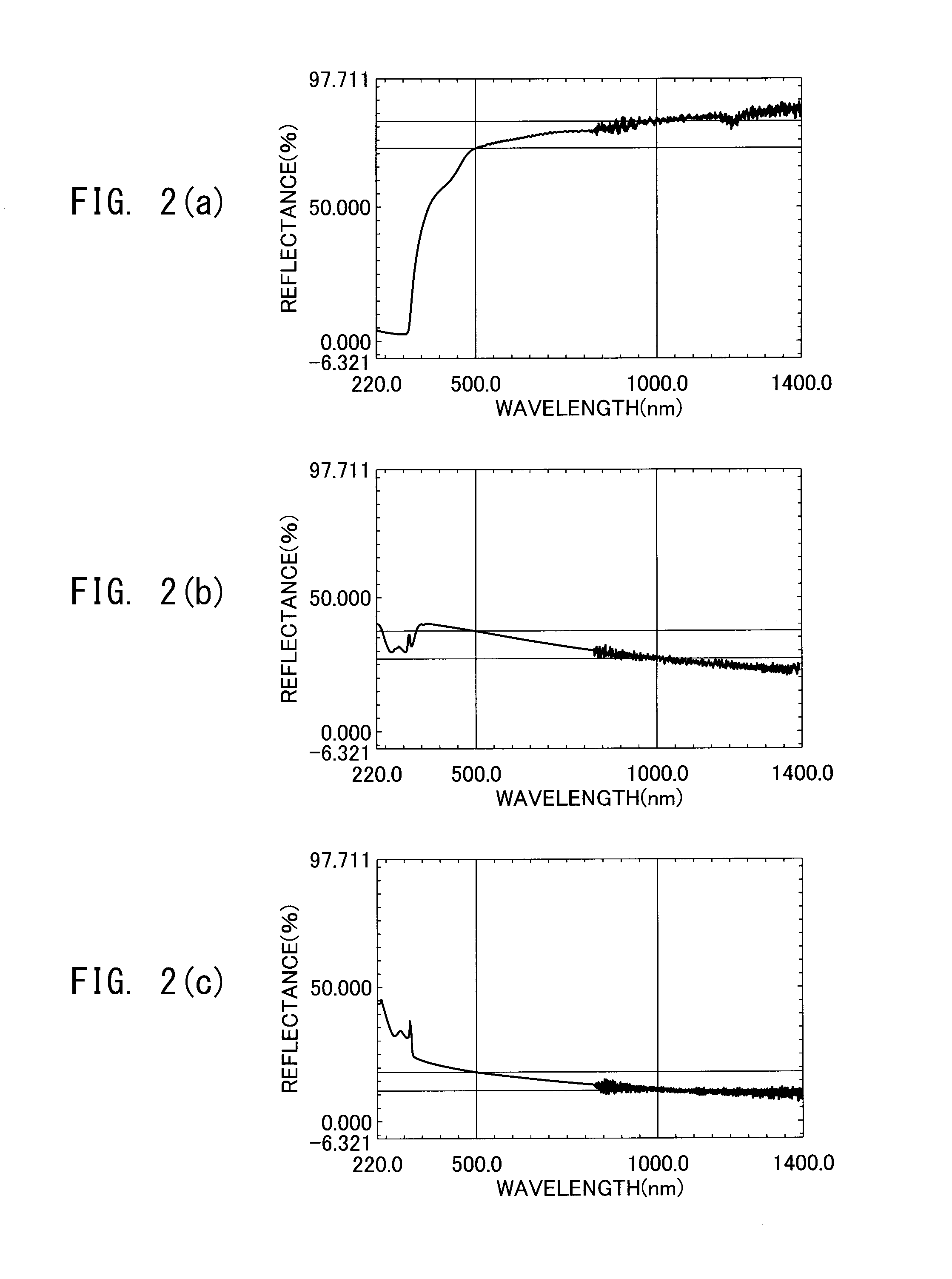
[0186]It is believed that this occurs because the laser reflectance by the solid electrolyte solution is 80% or more, particularly, 82% or more, and because the laser reflectance by the solid electrolyte layer is larger by 71% or more than the laser reflectance by the positive electrode active materi...


PUM

PropertyMeasurementUnit
Fractionaaaaaaaaaa
Fractionaaaaaaaaaa
Reflectanceaaaaaaaaaa

Abstract

A method for producing a laminate for a battery in which a first active material layer and a solid electrolyte layer are stacked, includes irradiating the laminate with a laser from a side of the laminate faced by the first active material layer to remove a part of the first active material layer. The reflectance of the laser by the solid electrolyte layer is 80% or more.

Description

TECHNICAL FIELD[0001]The present disclosure relates to a production method of a laminate for a battery, and more specifically, to a production method of a laminate for a battery where the number of processes involved in the production of the battery can be reduced, the short-circuiting of the battery can be prevented, and the performance of the battery can be enhanced.BACKGROUND ART[0002]In recent years, an all-solid battery in which an electrolytic solution is replaced by a solid electrolyte is attracting attention. Compared with a secondary battery using an electrolytic solution, the all-solid battery using no electrolytic solution does not cause decomposition, etc., of an electrolytic solution due to overcharge of the battery and has high cycle durability and high energy density.[0003]The inside of such an all-solid battery includes a laminate in which a positive electrode active material layer, a solid electrolyte layer and a negative electrode active material layer are stacked ...

Claims


Application Information

Patent Timeline
IPC IPC(8): H01M10/0585B23K26/36B23K26/38
CPCH01M10/0585B23K26/36B23K26/38H01M4/04H01M4/043H01M4/049H01M10/0413H01M10/0562B23K26/0624B23K26/352B23K26/361B23K2101/36B23K2103/08B23K2103/172B23K2103/50Y02E60/10Y02P70/50H01M10/052H01M2300/0068
Inventor KOJIMA, SHINJI
Owner TOYOTA JIDOSHA KK
Why Eureka
Try Eureka