Picture display method and apparatus

a technology of applied in the field of picture display method and apparatus, can solve the problems of large waste of light, dark picture, and dark display picture,

Inactive Publication Date: 2001-09-20
SONY CORP
View PDF0 Cites 71 Cited by
  • Summary
  • Abstract
  • Description
  • Claims
  • Application Information

AI Technical Summary

Problems solved by technology

The above-described conventional projection type picture display apparatus has a defect that, since the white light source (lamp), such as xenon lamp, metal halide lamp or halogen lamp, used as a light source, generally undergoes significant chronological changes, and is of short service life, the picture tends to become dark, while the lamp tends to be used up, such that the displayed picture tends to become dark or the lamp has to be exchanged during display of the picture.
The result is that much light is wasted to lower the utilization efficiency of light from the light source.
Moreover, the conventional projection type picture display apparatus has a defect that, because of the low utilization efficiency of light from the light source, a brighter light source needs to be used for obtaining the necessary brightness, and a defect that, since a larger light source needs to be used for realizing the necessary brightness, it becomes necessary to reduce the size of the projection type picture display apparatus.
The result is that the wavelength distribution of the separated colors depends on the wavelength distribution of the outgoing light of the original white light source to make difficult optimum color reproduction.
Moreover, in the white light source used in the conventional projection type picture display apparatus, brightness modulation is generally not possible or only narrow in brightness adjustment range, with the response time of brightness modulation being longer, such that, in the conventional projection type picture display apparatus, the displayed picture cannot be adjusted in brightness or can be adjusted only in a narrow range.
Also, if, in the conventional projection type picture display apparatus, the radiated light of the white light source is color-separated by, for example, a dichroic mirror so as to be illuminated on picture display light bulbs associated with respective color signals, it is difficult to adjust brightness of the light from one color to another.
Thus, with the conventional projection type picture display apparatus, fine color adjustment is difficult or can be realized only in a narrow range.

Method used


Image

  • Picture display method and apparatus
  • Picture display method and apparatus
  • Picture display method and apparatus

Examples


first embodiment

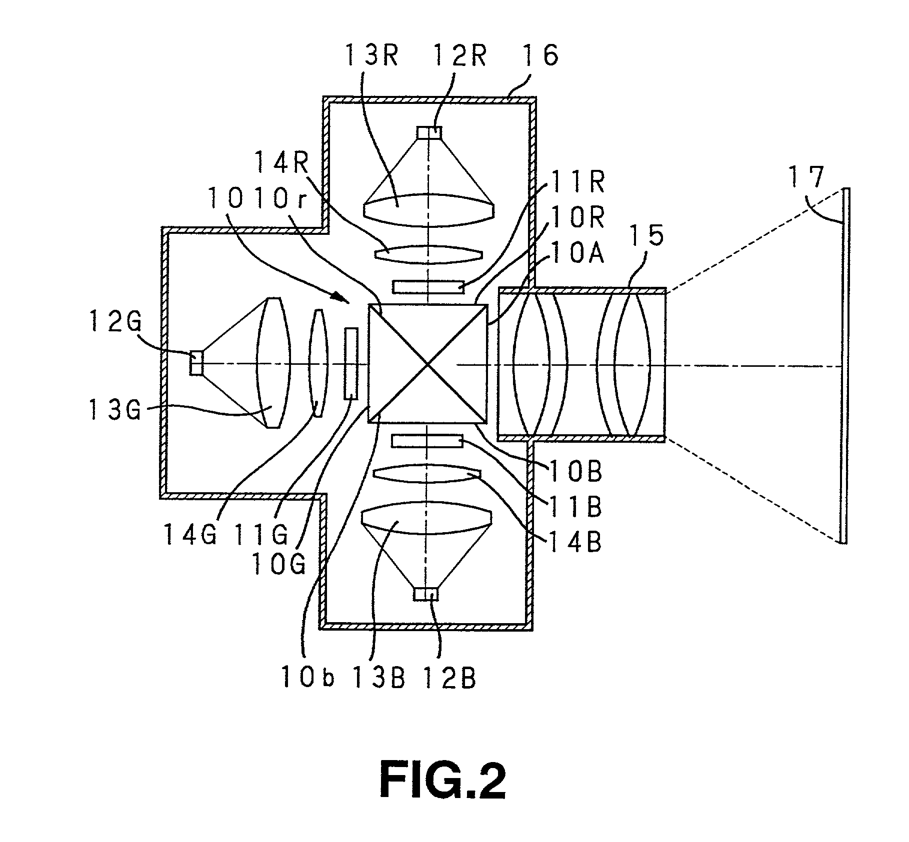
[0065] FIG. 2 is a schematic view for illustrating the structure of a projection type picture display device according to the present invention. This picture display device includes a cubic-shaped synthesis prism 10, a green picture display light bulb 11G arranged for facing a surface 10G of the synthesis prism 10, a red picture display light bulb 11R arranged for facing a surface 10R extending perpendicular to the surface 10G of the synthesis prism 10, and a blue picture display light bulb 11B arranged for facing a surface 10B extending parallel to the surface 10R of the synthesis prism 10. The picture display light bulbs 11R, 11G and 11B correspond to spatial modulation means in the present invention.

[0066] The picture display device further includes red light-emitting diode 12R, a green light-emitting diode 12G and a blue light-emitting diode 12b, arranged laterally of the picture display light bulbs 11R, 11G and 11B for operating as light sources for illuminating red, green and ...

second embodiment

[0093] Referring to FIGS. 8 and 9, the picture display device according to the present invention is explained.

[0094] In the present embodiment of the picture display device, plural light source devices 42, each comprised of plural light-emitting diodes having respective planar light radiating portions, are provided in place of the sole light-emitting diode 12 according to the previous embodiment. These light-emitting diodes are selectively driven so that the cross-sectional shape of the light beam radiated from the light source device 42 will correspond to the shape of the picture forming area of the picture display light bulb 11. The light source device 42 used in place of the light-emitting diode 12R is made up of plural red light-emitting diodes, while the light source device 42 used in place of the light-emitting diode 12G is made up of plural green light-emitting diodes 12G and the light source device 42 used in place of the light-emitting diode 12B is made up of plural blue li...

third embodiment

[0099] Referring to FIGS. 10 to 12, a picture display device of the present invention is explained.

[0100] FIG. 10 schematically shows the structure of a picture display device of the third embodiment. This picture display device includes a red light-emitting diode 44R, a green light-emitting diode 44G and a blue light-emitting diode 44B each having a circular planar shape of the light radiating portion. The picture display device of the present embodiment also includes light beam shape changing devices 50R, 50G and 50B between the field lens 14R and the picture display light bulb 11R, between the field lens 14G and the picture display light bulb 11G and between the field lens 14B and the picture display light bulb 11B, respectively.

[0101] FIG. 11 is a perspective view showing the structure of the light beam shape changing device 50 (generic appellation of 50R, 50G and 50B). This light beam shape changing device 50 includes two cylindrical lenses 51, 52. The radius of curvature of th...


PUM


Abstract

A picture display method and apparatus in which a light source is lengthened in service life and optimum color reproduction is realized, while the light utilization efficiency is improved to reduce the power consumption and the size of the apparatus. The red, green and blue illuminating light beams radiated from the light-emitting diodes 12R, 12G and 12R, are illuminated via relay lenses and field lenses on picture display light bulbs 11R, 11G and 11B and spatially modulated in intensity so as to be synthesized by a synthesis prism 10 and so as to be projected to an enlarged scale on a screen 17. The profile of the light radiating portions of the light-emitting diodes 12R, 12G and 12B are set so as to be the same or similar to the profile of a picture display area of each of the picture display light bulbs 11R, 11G and 11B in order that the profile of the light beam illuminated on the picture display area will be in keeping with the profile of the picture display area.

Description

[0001] 1. Field of the Invention[0002] This invention relates to a picture display method and apparatus for displaying a picture by spatially modulating the light outgoing from a light source and projecting the modulated light.[0003] 2. Description of the Related Art[0004] Among picture display apparatus used for the purpose of appreciating a picture, there is a projection type picture display apparatus in which the light outgoing from a light source is spatially modulated by a picture display light bulb for projection on a screen. This projection type picture display apparatus is classified into a front side projection type in which the picture is projected from the front side, such as a screen, and a back side projection type in which the picture is projected from the back side of the screen. As this projection type picture display apparatus, there is known such apparatus in which a white light source, including a discharge type xenon lamp, a metal halide lamp or a heat light emis...

Claims


Application Information

Patent Timeline
Patent Type & Authority Applications(United States)
IPC IPC(8): H04N9/31
CPCH04N9/3152H04N9/3155H04N9/3164H04N9/3182H04N9/3197
Inventor MATSUI, TAKESHIYOSHIDA, TAKUJIHASHIMOTO, SHUNICHITANAKA, YOSHINORIAKIMOTO, OSAMU
Owner SONY CORP
Why Eureka
Try Eureka