Image coding method and an image coding apparatus

a coding method and image technology, applied in image data processing, instruments, television systems, etc., can solve the problems of deteriorating coding efficiency, difficult to maintain consistency with another coding system, and relatively increasing the percentage of block mode data in the created coded signal, so as to prevent the coding efficiency from drastically deteriorating

Inactive Publication Date: 2001-09-20
GK BRIDGE 1
View PDF0 Cites 10 Cited by
  • Summary
  • Abstract
  • Description
  • Claims
  • Application Information

AI Technical Summary

Benefits of technology

[0006] The objective of the present invention is to provide an image coding apparatus and image decoding apparatus that will prevent the coding efficiency from drastically deteriorating even for those images that contain numerous blocks without movement information, quadrature conversion coefficient or significant form, etc. within one frame.
[0009] The first and second inventions can improve the coding efficiency by shortening the code word length of a coding mode with high hitting ratio.
[0012] The third and fourth inventions can easily perform coding / decoding using a correlation between blocks of the mode data, thus improving coding efficiency.
[0015] The fifth and sixth inventions can perform arithmetic coding / decoding by predicting a coding mode and adaptively switching to a probability model for which a coding mode with high appearance probability is set, thus improving coding efficiency.

Problems solved by technology

However, since the MMR system is a system in which processing is performed for the entire one frame input, it is difficult to maintain consistency with another coding system adopted in ITU-T H.261 and ISO / IEC MPEG, etc. in which one frame is divided into a plurality of blocks and processing is performed in block units.
However, the coding method that performs coding by dividing the above image block into the coding mode data that indicates the coding mode of said block and the data concerning the pixel values within said block has the problem that the percentage of the block mode data in the created coded signal relatively increases, deteriorating its coding efficiency in the case that blocks without movement information, quadrature conversion coefficient or significant form, etc. increases within one frame.

Method used


Image

  • Image coding method and an image coding apparatus
  • Image coding method and an image coding apparatus
  • Image coding method and an image coding apparatus

Examples


first embodiment

[0038] (First embodiment)

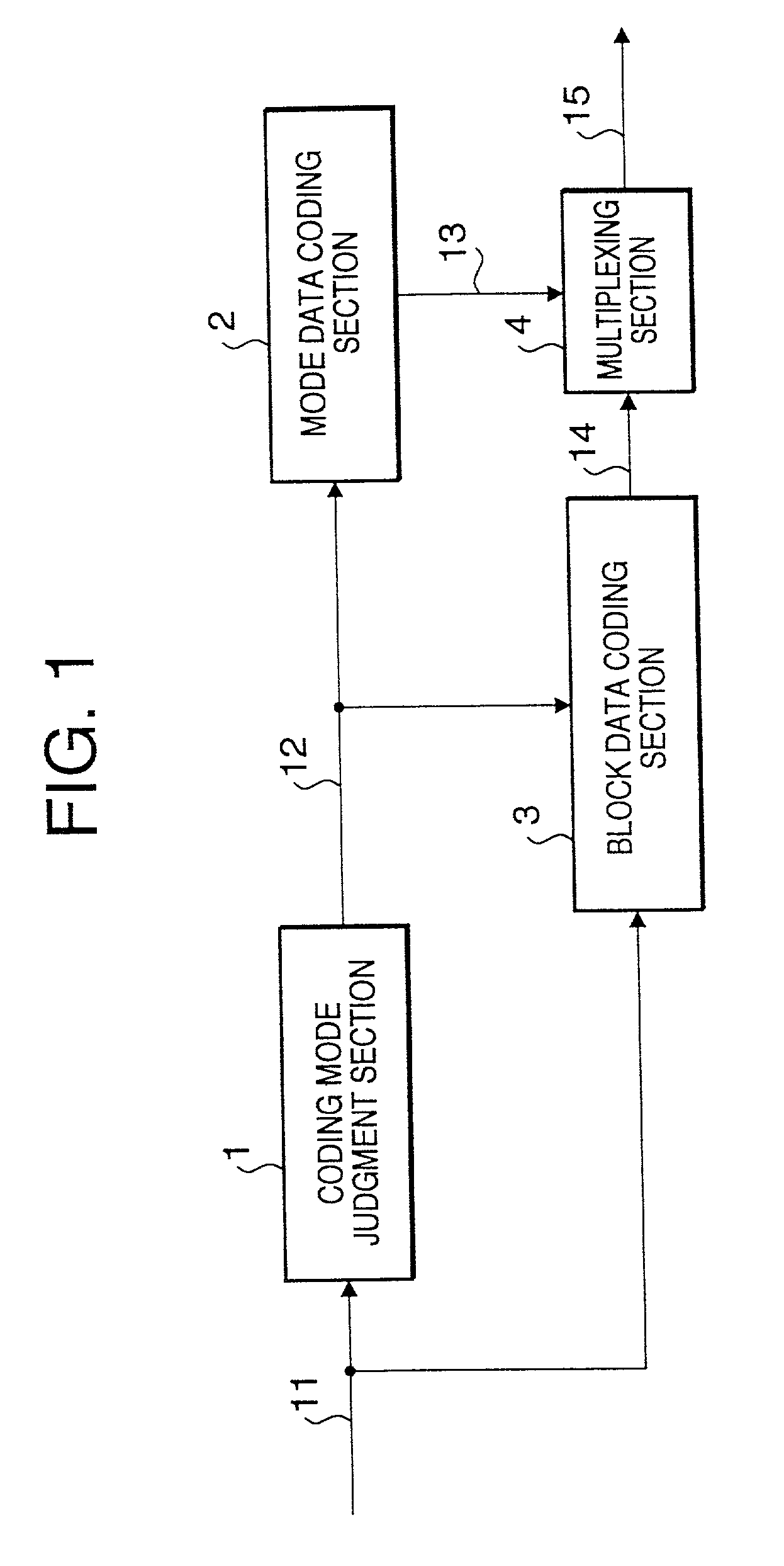
[0039] FIG. 1 shows a block diagram of the image coding system that constitutes the first embodiment of the present invention. The image coding system shown in said figure comprises coding mode judgment section 1 that outputs the coding mode data which indicates the coding mode of a pixel block to be coded, mode data coding section 2 that generates mode data code words using a code word table which will be described later, block data coding section 3 that generates a code word for the pixel value within the pixel block, and multiplexing section 4 that generates a coded image signal by multiplexing the code word regarding the mode data and the code word regarding the pixel value data. Here, code 11 indicates a pixel value signal of a block of a digital input image divided by the block division block which is not shown in the figure; code 12 indicates the coding mode data of the pixel block; code 13 indicates the code word regarding the mode data; code 14 indi...

embodiment 2

[0063] (Embodiment 2)

[0064] FIG. 8 is a block diagram of the image decoding system that relates to the second embodiment of the present invention. In said figure, the same signals as those in the first embodiment shown in FIG. 1 are assigned the same numbers and their explanations are omitted here.

[0065] This image decoding system comprises demultiplexing section 81 that separates the code word regarding the mode data and the code word regarding the block data from the coded image signal, mode data decoding section 82 that reproduces the coding mode data of the pixel block from the code word regarding the mode data, and block data decoding section 83 that reproduces the pixel value within the pixel block in the mode indicated by the reproduced mode data.

[0066] FIG. 9 is a functional block diagram of mode data decoding section 82. Mode data decoding section 82. comprises decoding section 91 that decodes the code word of the mode data, mode data storage section 92 that stores the mode...

third embodiment

[0081] (Third embodiment)

[0082] FIG. 10 shows a block diagram of the image coding system that relates to a third embodiment of the present invention. In said figure, the same functional blocks and same signals as those of the system shown in FIG. 1 are assigned the same numbers and their explanations are omitted.

[0083] The image coding system in the present embodiment comprises coding mode judgment section 1, memory 101 that stores coding mode data output from coding mode judgment section 1 for each block and outputs one-frame data together, mode data coding section 102 that codes one-frame coding mode data together to create code words, block data coding section 3, memory 103 that stores the code word regarding the block data for each block and outputs one-frame data together, and multiplexing section 104 that multiplexes the code word regarding one-frame mode data with the code word regarding the block data of each pixel block within the same frame to generate a coded image signal...


PUM


Abstract

An image coding method codes each block of a digital image divided into two-dimensional blocks, each block having a plurality of pixels. A coding mode for a target block is determined to output mode information of the target block. A codeword of the mode information of the target block is output, the codeword being determined based on a combination of the mode information of the target block and the mode information of previously coded blocks at a periphery of the target block, or a combination of the mode information of the target block and temporary mode information replacing the mode information of the blocks at the periphery of the target block when the blocks at the periphery are out of an image. Pixel data in the target block is coded according to the mode information of the target block.

Description

[0001] This is a division of U.S. patent application Ser. No. 09 / 091,922, filed Jun. 25, 1998, pending, which was the National Stage of International Application No. PCT / JP9764034, filed Nov. 6, 1997 the contents of which are expressly incorporated by reference herein in its entirety. The International Application was not published in English.[0002] The present invention relates to an image coding apparatus and an image decoding apparatus for coding and decoding digital images, and also relates to recording media in which image coding / decoding programs are stored.[0003] One of known conventional image coding systems requiring reversibility is the MMR (Modified Modified Read) system which is used in facsimile applications. However, since the MMR system is a system in which processing is performed for the entire one frame input, it is difficult to maintain consistency with another coding system adopted in ITU-T H.261 and ISO / IEC MPEG, etc. in which one frame is divided into a pluralit...

Claims


Application Information

Patent Timeline
Patent Type & Authority Applications(United States)
IPC IPC(8): G06T9/00H04N7/26H04N7/30H04N19/593
CPCH04N19/176H04N19/46H04N19/196H04N19/13H04N19/60H04N19/593H04N19/463H04N19/91H04N19/157H04N7/24
Inventor MATSUMOTO, TAISUKE
Owner GK BRIDGE 1
Why Eureka
Try Eureka