Control system for controlling variable valve type internal combustion engine

a control system and internal combustion engine technology, applied in electrical control, machines/engines, non-mechanical valves, etc., can solve the problems of difficult to obtain the desired operation of the engine, electromagnetic actuators have a limitation in speeding up the actuation of the intake valve, and the reduction of load is almost impossible or at least very difficul

Inactive Publication Date: 2001-09-27
NISSAN MOTOR CO LTD
View PDF0 Cites 36 Cited by
  • Summary
  • Abstract
  • Description
  • Claims
  • Application Information

AI Technical Summary

Problems solved by technology

However, even in the above-mentioned measures, it is difficult to obtain a desired operation of the engine at the time when the engine is under high-speed and low-load operation because of the nature of the electromagnetic actuators.
That is, the electromagnetic actuators have a limitation in speeding up the actuation to the intake valves.
In other words, under high-speed operation of the engine, reduction of load i

Method used


Image

  • Control system for controlling variable valve type internal combustion engine
  • Control system for controlling variable valve type internal combustion engine
  • Control system for controlling variable valve type internal combustion engine

Examples


first embodiment

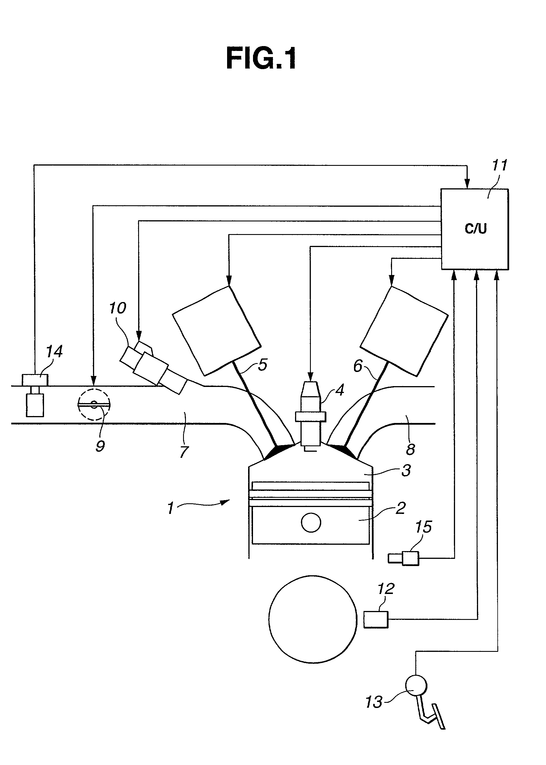
[0025] Referring to FIG. 1, there is schematically shown a variable valve type internal combustion engine 1 to which a control system of the present invention is practically applied.

[0026] The engine 1 has a plurality of cylinders (only one is shown) each having a piston 2 slidably received therein. In each cylinder, there is defined a combustion chamber 3 above the piston 2. An ignition plug 4 is exposed to the combustion chamber 3. An intake passage 7 is connected to intake openings of the combustion chambers 3 through an intake manifold and an exhaust passage 8 is connected to exhaust openings of the combustion chambers 3 through an exhaust manifold. Electromagnetically actuated intake and exhaust valves 5 and 6 are arranged to open and close the intake and exhaust openings.

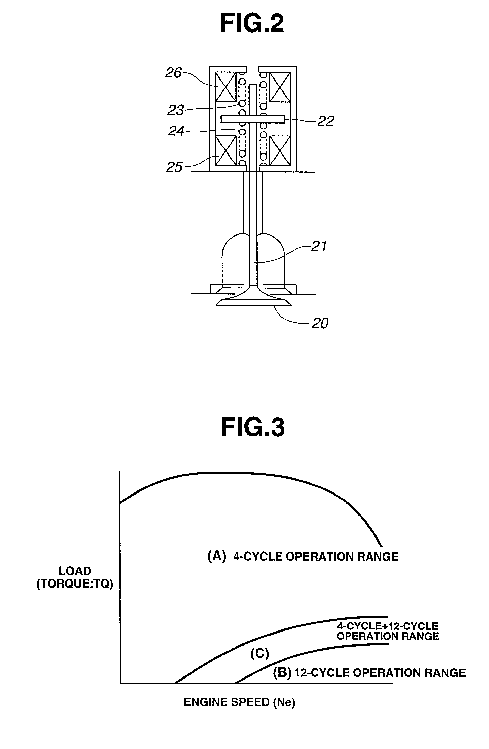
[0027] The intake and exhaust valves 5 and 6 are actuated by electromagnetic actuators, such as one as shown in FIG. 2.

[0028] As shown in FIG. 2, the electromagnetic actuator comprises an armature plate 22 whi...

second embodiment

[0045] In the following, description will be directed to the present invention.

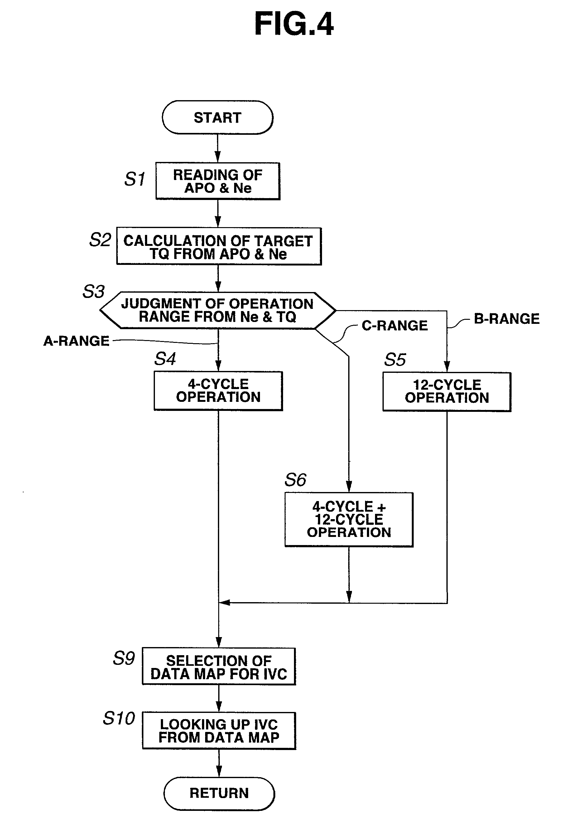
[0046] In the second embodiment, as is seen from the graph of FIG. 7, in a high-load range "D", a two (2)-cycle operation is carried out by the engine 1.

[0047] As is shown in FIG. 9, in 2-cycle operation, each cylinder is subjected to the two stroke cycle, in which during downward movement of the piston (namely, in the middle of the explosion stroke after the piston has reached the top dead center "TDC"), the intake and exhaust valves are opened at generally same time to bring about the air intake and gas discharge simultaneously at the time near (namely, just before and after) the bottom dead center "BDC" of the piston, and during upward movement of the piston (namely, in the middle of the piston lifting stroke after the piston has reached the bottom dead center "BDC"), the intake and exhaust valves are closed at generally same time to bring about a so-called compression stroke, and when the piston comes...


PUM


Abstract

A variable valve type internal combustion engine has cylinders and electromagnetically actuated intake and exhaust valves for each cylinder. The intake air amount fed to the cylinder is controlled by controlling the close timing of the intake valve. A control system for the engine, comprises an operation range judging section that judges an operation range assumed by the engine; a variable cycle operating section that switches the operation of the engine between 4-cycle operation and a different cycle operation in accordance with the judgment made by the operation range judging section, the different cycle operation being of an operation whose cycle is different from the 4-cycle; and an intermediate variable cycle operating section that allows part of the cylinders of the engine to carry out 4-cycle operation and the remaining part of the cylinders to carry out the different cycle operation when the operation range judging section judges that the engine is under an intermediate operation range between an operation range provided by the 4-cycle operation and an operation range provided by the different cycle operation.

Description

[0001] 1. Field of the Invention[0002] The present invention relates in general to control systems for controlling internal combustion engines of a variable valve type wherein open / close movements of the intake and exhaust valves are controlled in accordance with an operation condition of the engine, and more particularly to the control systems of a type that controls the intake air amount by controlling the close timing (viz., open period) of each intake valve to carry out a so-called non-throttle operation of the engine. More specifically, the present invention is concerned with the control systems of a type that allows the engine to work under various operation cycles.[0003] 2. Description of the Prior Art[0004] Nowadays, variable valve type internal combustion engines are widely employed in motor vehicles for the superiority of the engine. In fact, fuel consumption and driveability under lower speed and low load engine operation are improved and at the same time due to increased...

Claims


Application Information

Patent Timeline
IPC IPC(8): F01L1/38F01L9/04F01L13/00F02B75/02F02B1/04F02B69/06F02B75/18F02D13/02F02D41/00F02D41/30
CPCF02B1/04F02B69/06F02B75/021F02B2075/025F02B2075/027F02D41/008F02D41/3058
Inventor MIURA, HAJIME
Owner NISSAN MOTOR CO LTD
Why Eureka
Try Eureka