Valve control device of internal combustion engine

a control device and internal combustion engine technology, applied in the direction of valve arrangements, machines/engines, mechanical equipment, etc., can solve the problems of difficult to obtain difficult to achieve the desired engine performance, and improved engine fuel consumption

Inactive Publication Date: 2001-10-04
NISSAN MOTOR CO LTD
View PDF0 Cites 44 Cited by
  • Summary
  • Abstract
  • Description
  • Claims
  • Application Information

AI Technical Summary

Problems solved by technology

That is, the close timing of the intake valve is not appropriately controlled.
In this case, it is difficult to obtain a desired engine performance, particularly, improved fuel consumption of the engine.
However, due to inevitability of using such two me

Method used


Image

  • Valve control device of internal combustion engine
  • Valve control device of internal combustion engine
  • Valve control device of internal combustion engine

Examples


first embodiment

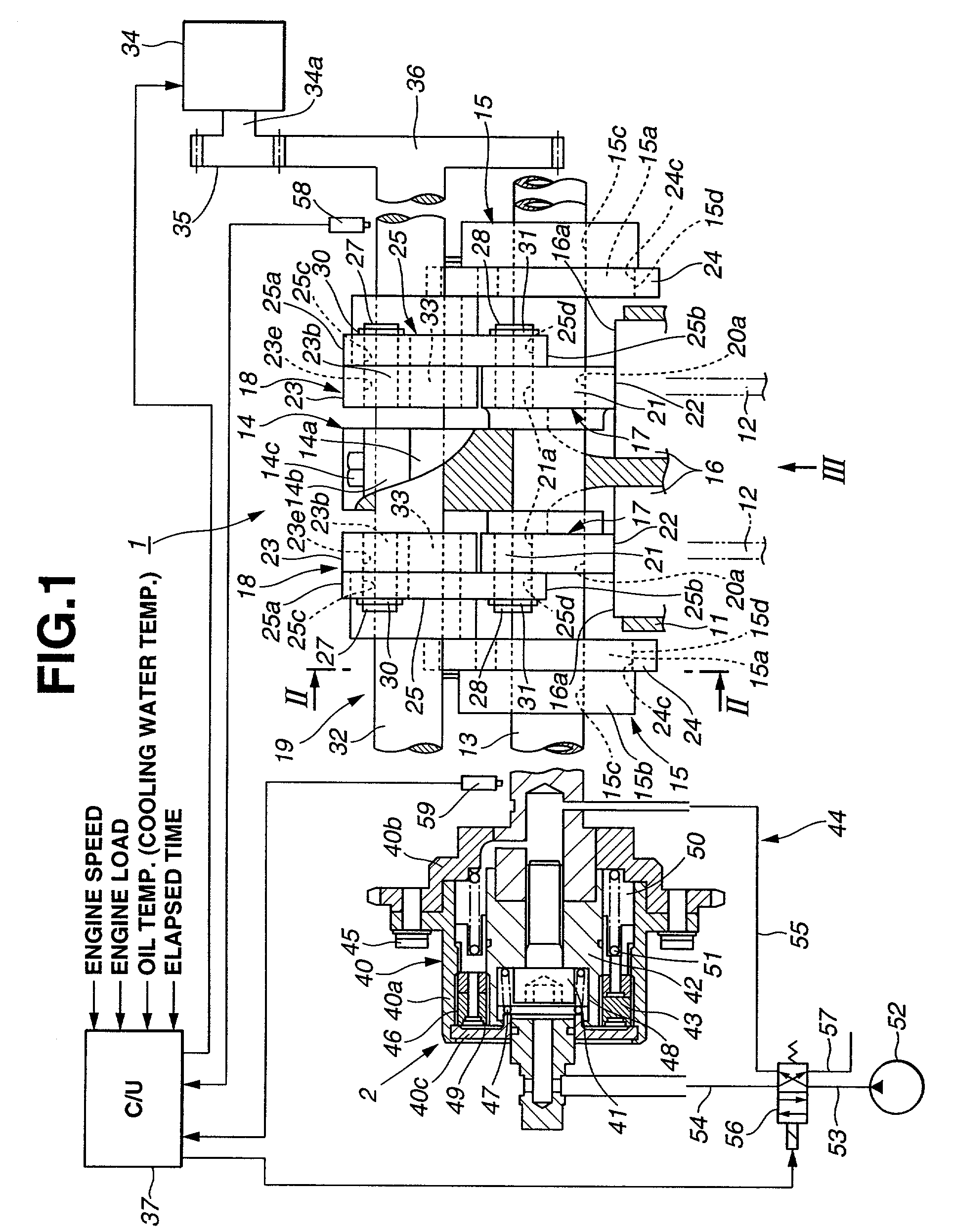
[0041] The valve control device of the first embodiment comprises generally a first variable valve actuating mechanism 1 that varies or controls the operating angular range of the intake valves 12, a second variable valve actuating mechanism 2 that varies or controls the center angle of the operating angular range of the intake valves 12 and a control unit 37 that controls the first and second variable valve actuating mechanism 1 and 2 in accordance with operation condition of the engine. The control unit 37 comprises a micro-computer including CPU, RAM, ROM and input and output interfaces.

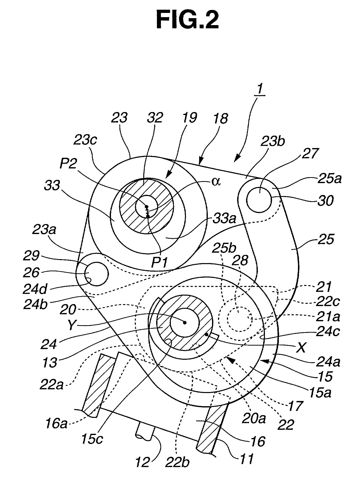
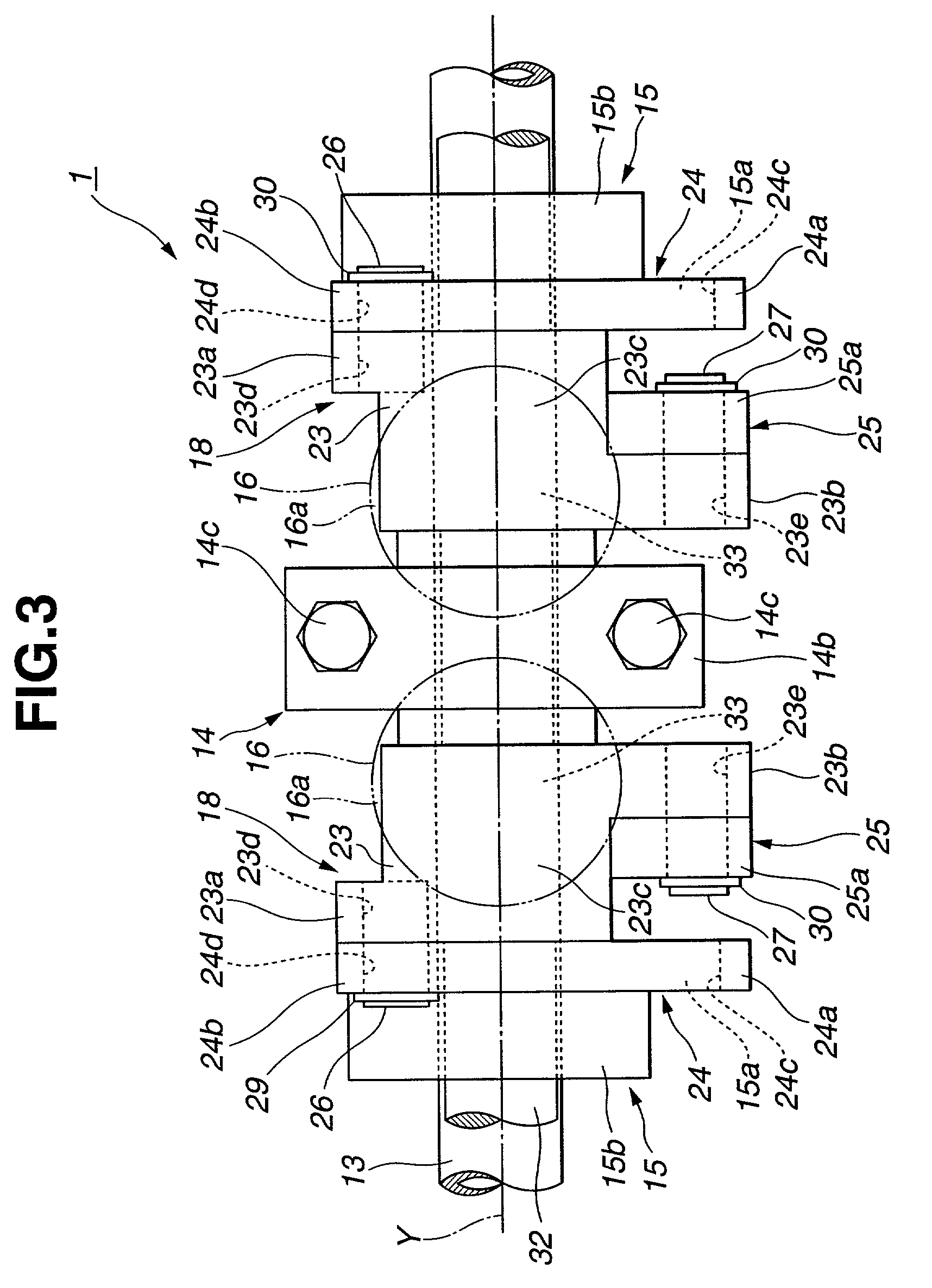
[0042] As is seen from FIGS. 1 to 3, the first variable valve actuating mechanism 1 generally comprises a hollow drive shaft 13 that is rotatably held by bearings 14 (only one is shown) mounted on the cylinder head 11, two eccentric drive cams 15 that are tightly disposed on the drive shaft 13, two swing cams 17 that are swingably or rotatably disposed on the drive shaft 13 and slidably contactabl...

second embodiment

[0089] FIGS. 12 to 14 show an intake system of an internal combustion engine to which the second embodiment is practically applied. As will be described in detail in the following, in this intake system, there is arranged a swirl control valve 105 that enhances a mixture flow in the intake system.

[0090] As is shown in FIG. 12, intake air is led into a combustion chamber 104 through an intake manifold 102 and an intake port 103. As is seen from FIG. 14, the intake port 103 is branched into two intake ports 103a and 103b each having an electromagnetically actuated intake valve 12 (see FIG. 12). That is, upon lifting of the intake valves 12, intake air is led into the combustion chamber 104.

[0091] As is seen from FIG. 12, the swirl control valve 105 is installed in the manifold near the intake port 103. As is seen from FIGS. 13 and 14, the swirl control valve 105 has a cut 105a at a portion facing the intake port 103a. Accordingly, when the swirl control valve 105 assumes its close pos...

third embodiment

[0098] The valve control device of the third embodiment comprises generally a first variable valve actuating mechanism 1' that continuously varies the operating angular range (or valve lift degree) of the intake valves 12 and a second variable valve actuating mechanism 2' that continuously varies the center angle of the operating angular range and a control unit 37 that controls the first and second variable valve actuating mechanisms 1' and 2' in accordance with operation condition of the engine.

[0099] In the third embodiment, a hydraulically controlled step motor 34' is used. Between the step motor 34' and the oil pump 52, there is installed a solenoid type switching valve 60 that is controlled by the control unit 37. That is, based on instruction signal from the control unit 37, the control shaft 32 is rotated stepwise changing the angular position thereof.

[0100] That is, based on the engine speed, load, oil temperature, elapsed time from engine start, etc., the control unit 37 s...


PUM


Abstract

A first variable valve actuating mechanism varies an operating angular range of an intake valve, a second variable valve actuating mechanism varies a center angle of the operating angular range, and a control unit controls, through the first and second variable valve actuating mechanisms, the operating angular range and the center angle in accordance with an operation condition of the engine. The control unit is configured to carry out, in a low-output operation range of the engine, advancing the center angle with increase of the engine output while making the variation of the center angle larger than that of the operating angular range; and in a middle-output operation range of the engine, increasing the operating angular range with increase of the engine output while making the variation of the operating angular range larger than that of the center angle.

Description

BACKGROUND OF INVENTION[0001] 1. Field of Invention[0002] The present invention relates in general to control devices for controlling internal combustion engines, and more particularly to the control devices of a type that, for achieving desired operation of the engine, controls the movement of intake and / or exhaust valves in accordance with operation condition of the engine. More specifically, the present invention is concerned with improvement of such control devices, by which the lift characteristics (viz., operating angular range, center angle of the range, etc.,) of intake and / or exhaust valves are controlled in accordance with the engine operation condition.[0003] 2. Description of Prior Art[0004] Hitherto, various control devices have been proposed and put into practical use in the field of automotive internal combustion engines. Among them, there is a type that controls an operating angular range of an intake valve and a center angle of the operating angular range in accorda...

Claims


Application Information

Patent Timeline
IPC IPC(8): F01L13/00
CPCF01L13/0021F01L13/0026
Inventor NOHARA, TSUNEYASUSUGIYAMA, TAKANOBUTAKEMURA, SHINICHI
Owner NISSAN MOTOR CO LTD
Why Eureka
Try Eureka