Roll seal control valve

a seal control valve and valve body technology, applied in the direction of diaphragm valves, positive displacement liquid engines, engine diaphragms, etc., can solve the problems of cycling problems, problems in liquid systems other than water, and the most of wear and damage of motors and pumps

Inactive Publication Date: 2001-10-25
AUSTIN CARY M
View PDF0 Cites 7 Cited by
  • Summary
  • Abstract
  • Description
  • Claims
  • Application Information

AI Technical Summary

Problems solved by technology

If the use is such that the small pressure tank is quickly drained, the motor is switched on, the pump fills the pressure tank quickly, the pump switches off, and then as the tank is quickly drained, the pump switches on again. so Most of the wear and damage to the motors and the pumps is caused by the numerous repeated starts and stops of the system.
Also the problem arises in systems that have irregular irrigation, for example, golf courses where different flow rates are required.
Also the system with cycling problems exists with tall buildings where because of the building height it is necessary to have controls for different levels of the building, and different flow rates.
The problem also exists in liquid systems other than water.
This will cause the motor to cycle on and off.
However, these bypasses exhibited certain problems, one of which being the noise caused by the pressure of the liquid flowing through a small opening.
Also, the small opening is susceptible to being clogged with debris.

Method used


Image

  • Roll seal control valve
  • Roll seal control valve
  • Roll seal control valve

Examples


Embodiment Construction

:

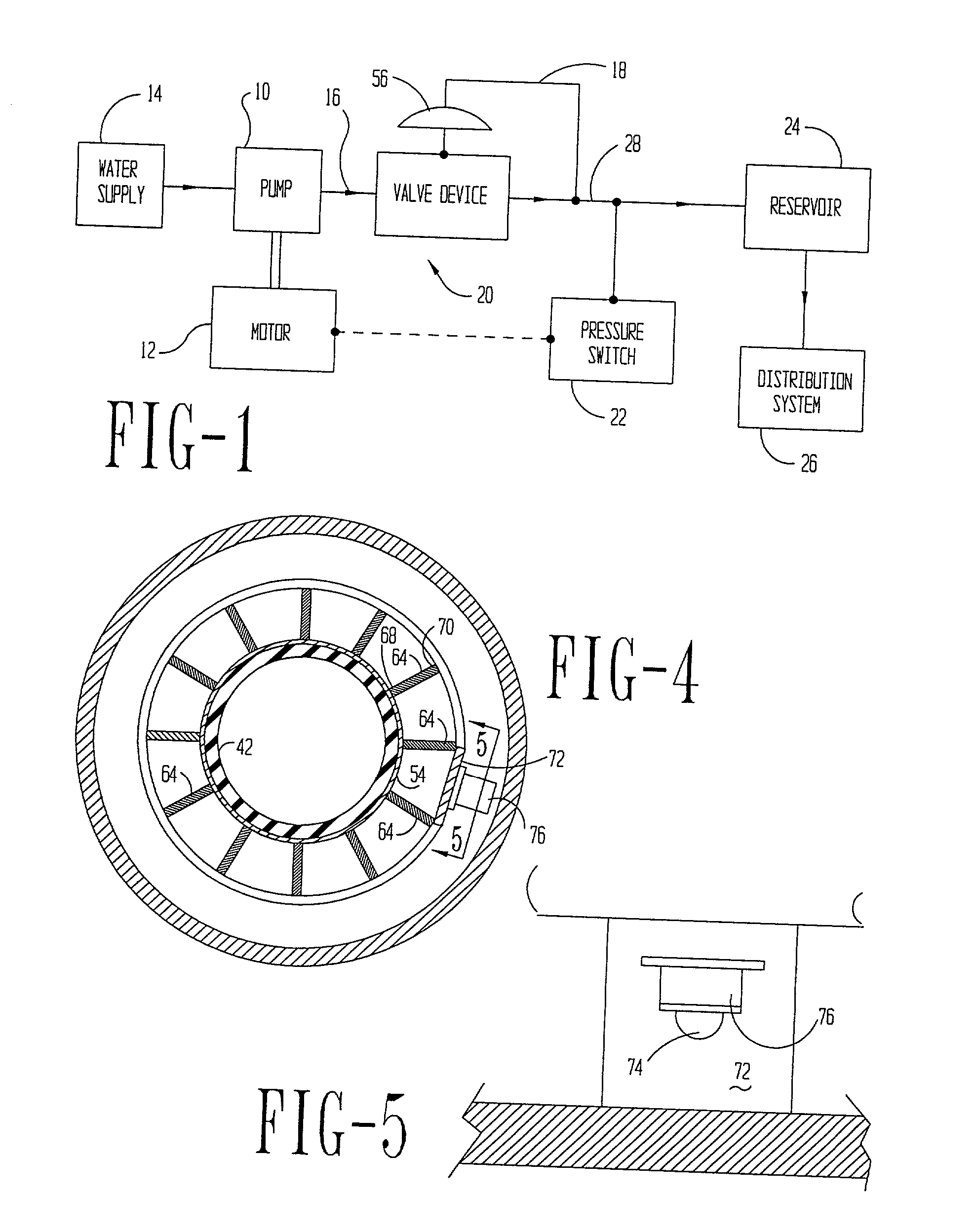
[0031] An embodiment of the valve device according to this invention is designed to work with motor driven pumps which are non-positive displacement. The valves would also work with a positive displacement pump if the pump were powered by a motor which would reduce its speed via increased back pressure on the pump. Usually the valves are used on pumps having constant velocity and the flow rate of the pumps decrease with increased pressure. The most common pumps of this type are centrifugal pumps.

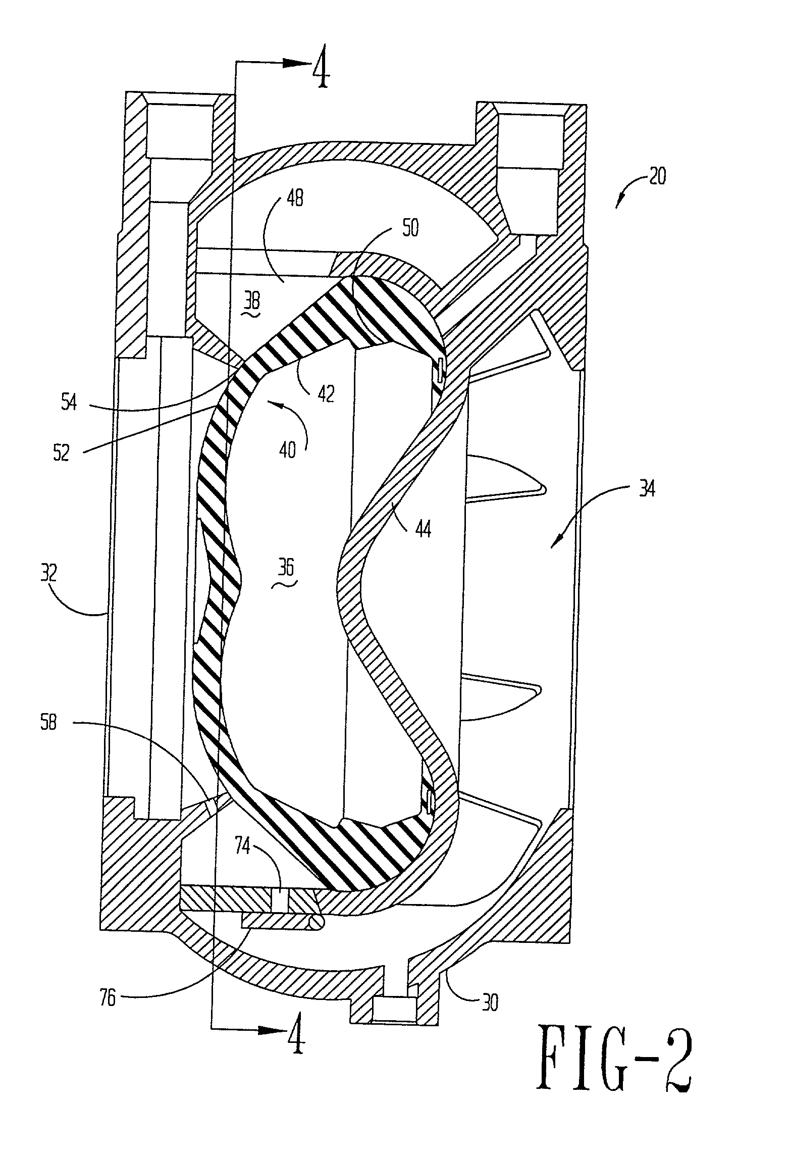
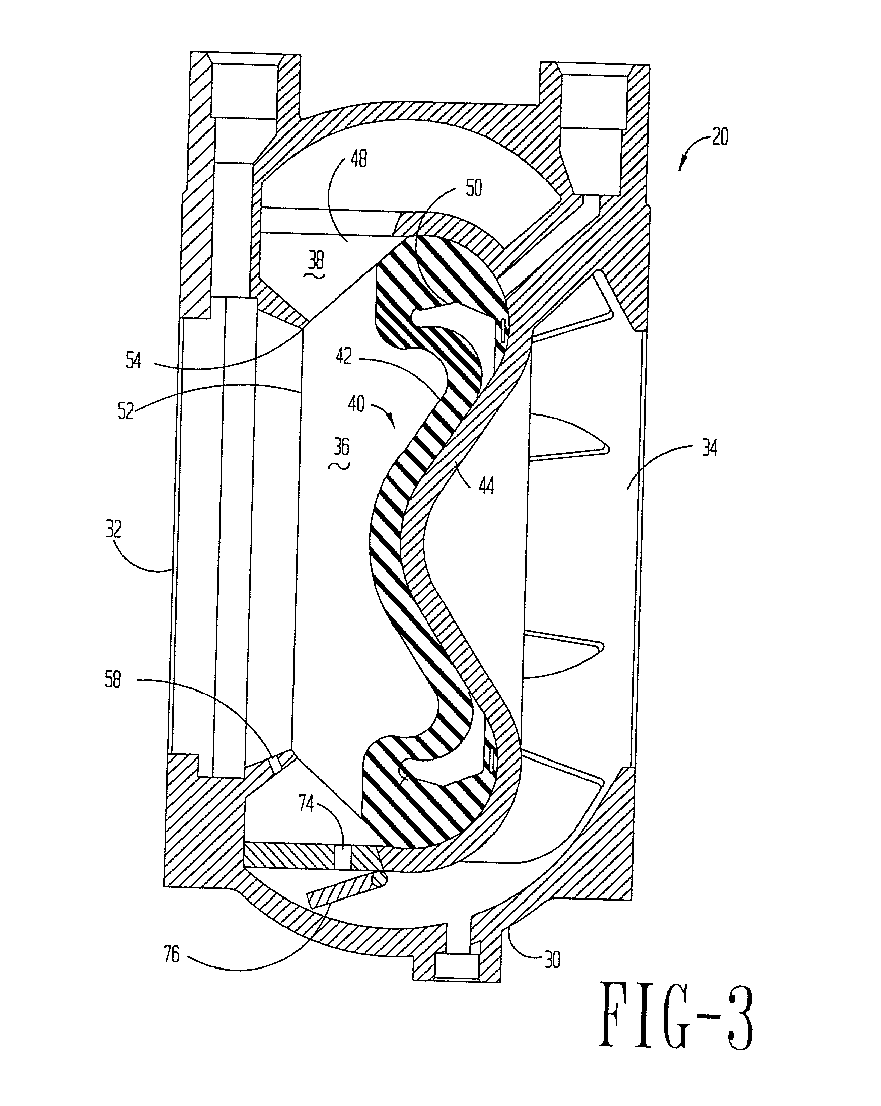
[0032] The valve devices of this invention will always include a valve seat and a valve element that moves relative to the valve seat. Often the valve seat and the valve each have a plane surface, and the surfaces are always parallel in their relationship. In some cases the valve surfaces are conical. Some valves have a toothed surface to cause a zigzag spray pattern from the partially opened valve instead of a flat spray pattern. Sometimes a butterfly or gate valve in combination with a se...


PUM


Abstract

A water system uses a pressure reservoir of an extremely small size. A valve device is placed between a water pump and the pressure reservoir. The valve device has a constant outlet pressure to limit the flow from the pump at high pressures. The pump is turned on and off by a pressure on/off switch. The valve device maintains the pressure to the reservoir at or below the off switch pressure except for a trickle flow. The trickle flow fills the reservoir when there is little or no water usage from the reservoir. The trickle flow is achieved by preventing the surfaces to seal by a projection or notch the valve surfaces of the valve device. Each time the valve opens any debris is washed from the valve surfaces thereby keeping them free of debris.

Description

CROSS REFERENCE TO RELATED APPLICATION:[0001] This is a continuation in part of my prior application on this subject matter filed Apr. 4, 2000, Ser. No. 09 / 542,312 now in Issue, Batch F21, which was a continuation in part of my prior application on this subject mater filed Feb. 1, 1999, Ser. No. 09 / 243,730 now U.S. Pat. No. 6,109,296 which was a continuation in part of my application filed Jul. 2, 1997, Ser. No. 08 / 886,905 now U.S. Pat. No. 5,988,984 which was a continuation in part of my application filed Apr. 24, 1995, Ser. No. 08 / 427,448 (now abandoned) which was a continuation in part of my application filed Aug. 6, 1993, Ser. No. 08 / 103,340 (now abandoned). Specific reference is made to the above documents.BACKGROUND OF THE INVENTION:[0002] (1) Field of the Invention[0003] This invention relates to liquid pumps and liquid systems and more particularly to a valve and system to prevent a motor driving a liquid pump from cycling, that is quickly and repeatedly turning off and on. ...

Claims


Application Information

Patent Timeline
Patent Type & Authority Applications(United States)
IPC IPC(8): F16K31/12F16K31/126F16L55/04
CPCE03B5/02F04B23/02F04B2205/063F04D13/16F04D15/0209F16K7/17Y10T137/87499Y10T137/87555
Inventor AUSTIN, CARY M.
Owner AUSTIN CARY M
Why Eureka
Try Eureka