Polishing device and polishing pad component exchange device and method

a technology of component exchange and polishing device, which is applied in the direction of grinding machine components, metal-working machine components, manufacturing tools, etc., can solve the problems of inability to manually enter the polishing device in person, the polishing device is worn, and the utilization efficiency of the polishing device is reduced

Inactive Publication Date: 2001-11-15
NIKON CORP
View PDF0 Cites 34 Cited by
  • Summary
  • Abstract
  • Description
  • Claims
  • Application Information

AI Technical Summary

Benefits of technology

[0015] Regarding this polishing device, the polished object is retained by the object retention mechanism while its plane to be polished faces upward, whereas the polishing plane of the polishing pad component which is retained by the pad retention mechanism is pressed onto the plane to be polished from above, whereas the plane to be polished is polished based on the relative shift of the two (relative rotational shift) caused by the shift mechanism. In such a case, the polishing plane of the polishing pad component is generally smaller than the plane to be polished, as a result of which the polishing frequency tends to become high. Since the polishing pad component is constituted to entail automatic attachments / detachments and exchanges in relation to the pad retention mechanism using the fixation and retention mechanism and the shift mechanism which enable a shift to the polishing pad component exchange position, a used polishing pad component can be automatically exchanged with a new polishing pad component, so that the polishing pad exchanging operative efficiency can be improved.
[0025] The method of the present invention for exchanging polishing pad components, on the other hand, is constituted to utilize the polishing device of the present invention described above for exchanging polishing pad components in relation to the pad retention mechanism. If this method is implemented, the polishing pad component exchanging operative efficiency can be improved.

Problems solved by technology

When a wafer is polished by using any of the aforementioned polishing devices, its pad becomes worn as a result of polishing, and therefore, the pad is subjected to dressing and washing operations by using a pad conditioning device after one or multiple wafers have been polished for the purpose of roughening (repairing) the pad.
The peeling of the polishing cloth and its pasting onto the attachment panel, however, are cumbersome during such a polishing cloth reloading operation, and furthermore, advanced skills are required, as a result of which the utilization efficiency of the polishing device decreases.
Even in such a method, however, a manual operation wherein a worker enters the polishing device in person is unavoidable, and cumbersome bolt attachment and detachment procedures are required for exchanging polishing pad components.
For this reason, the diameter of the disc (as well as of the polishing pad component) is large in comparison with the wafer diameter, as a result of which the structure of the automatic exchange device for exchanging such large polishing pad components becomes large and complicated, accompanied by high production costs.
Such a CMP device wherein the polisher diameter is small in comparison with the wafer diameter, however, is characterized by a high utilization efficiency of the polishing plane (pad plane) of the polisher (polishing pad component), and accordingly, the depressions of the polishing plane of the polisher tend to become congested.
As has been mentioned above, furthermore, the polishing pad component is attached to the spindle axle while its pad plane faces downward, as a result of which it becomes difficult to achieve a favorable precision during the exchange operation, and the operative efficiency is problematically unfavorable.

Method used


Image

  • Polishing device and polishing pad component exchange device and method
  • Polishing device and polishing pad component exchange device and method
  • Polishing device and polishing pad component exchange device and method

Examples


application example 2

[0114] Application Example 2

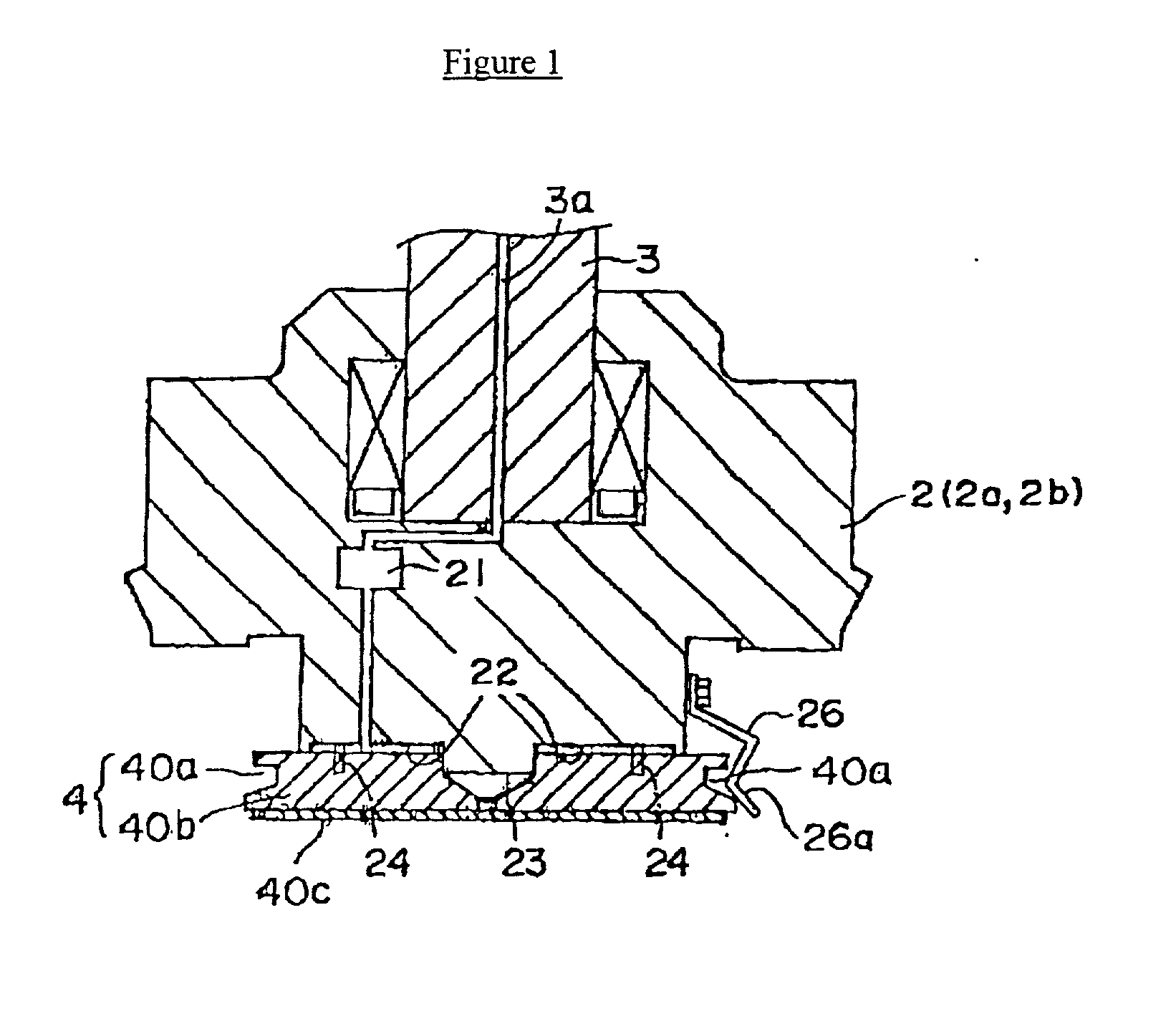
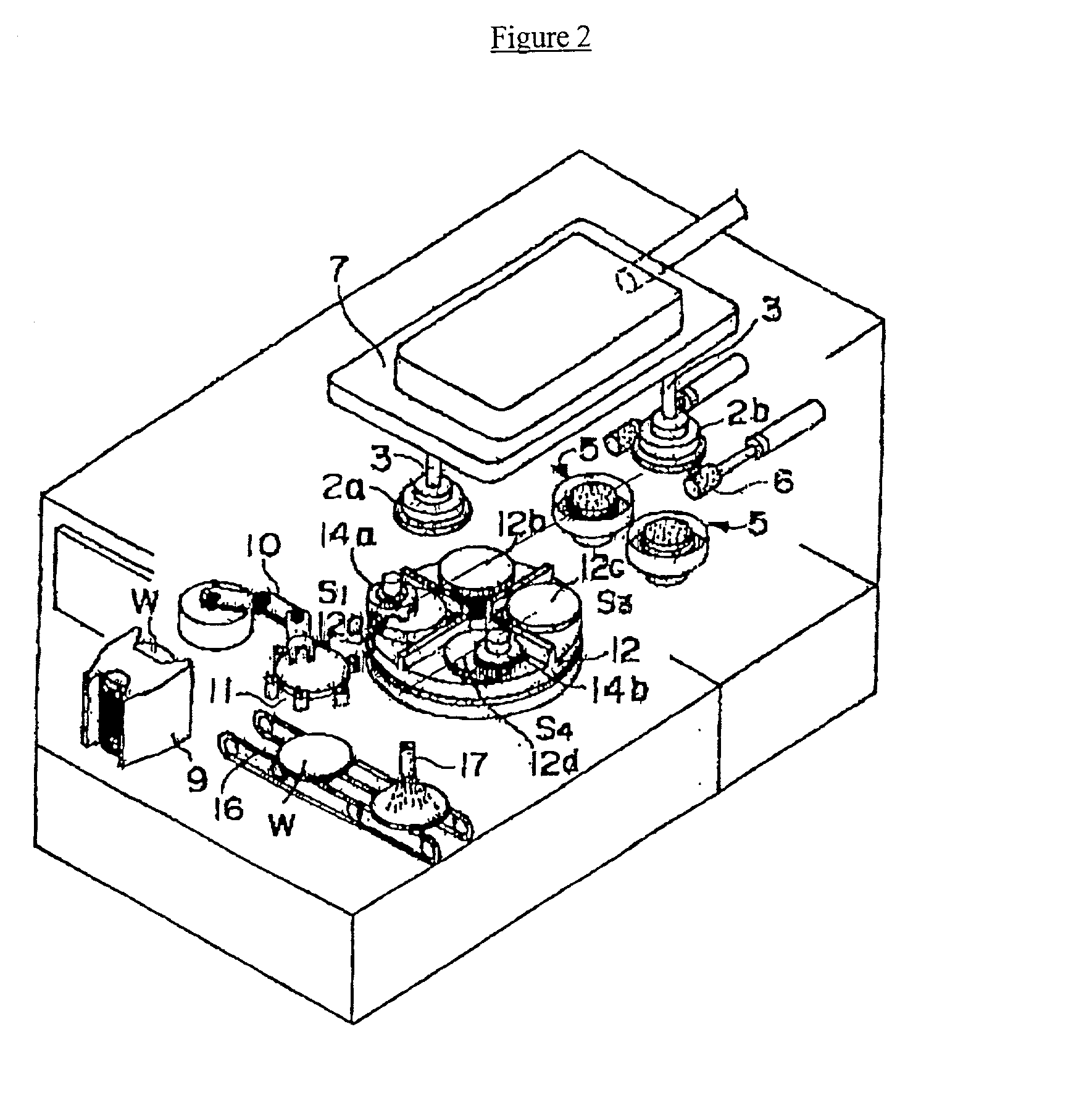
[0115] In this example, too, a pad support method based on vacuum suction was used, and a polishing pad component (4) which had been obtained by attaching 101000 / SUBA400 (polishing pad manufactured by Rodell Co.; diameter: 150 mm) onto a polisher supporter constituted by an alumina substrate was set on the polishing pad storage shelf (19) by means of a manual operation by using a CMP polishing device wherein the polishing pad component was smaller than the polishing object.

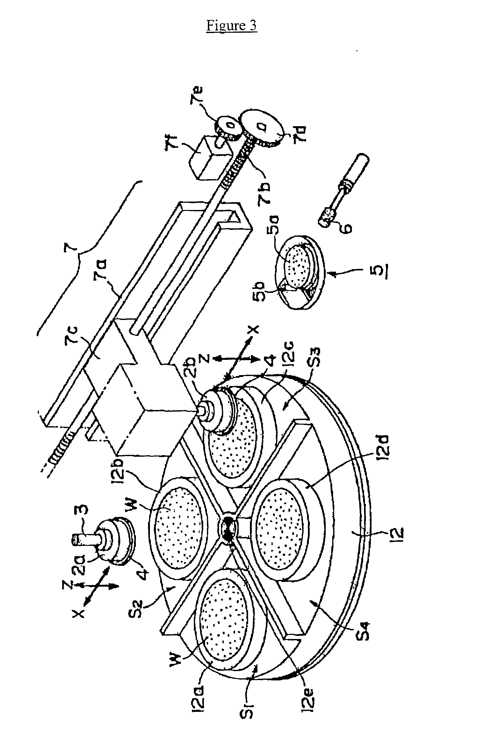
[0116] Next, the automatic exchange button of the front panel of the CMP device was pressed by an operator. As a result, the air cylinder (8) was activated, and after the side of a used polishing pad component (4) which was being drawn toward the polishing head (2) based on vacuum suction had been gripped by the exchange arm, the vacuum suction force which had been responsible for the fixation of the polishing pad component (4) was turned OFF. Next, the exchange arm, which had been grip...

application example 3

[0118] Application Example 3

[0119] A magnetic fixation method was used as a method for fixing a polishing pad component in this example. Regarding this example, the polishing pad component (4) was constituted by pasting 101000 / SUBA400 (polishing pad manufactured by Rodell Co.; diameter: 150 mm) onto a polisher supporter constituted by a magnet (SUS410) with a thickness of 0.2 mm, and an unused polishing pad component (4) thus constituted was set on the polishing pad storage shelf (19).

[0120] Next, the automatic exchange button of the front panel of the CMP device was pressed by an operator. As a result, the exchange arm gripped the used polishing pad component (4), and subsequently, the electromagnet which had been responsible for the fixation of the polishing pad component (4) was turned OFF. The exchange arm transported the used polishing pad component (4) while still gripping it, which was then stored in the lowermost layer of the storage shelf (19). Subsequently, the unused poli...

application example 4

[0121] Application Example 4

[0122] A gadget fixation method was utilized as a method for fixing the polishing pad component (4) in this example. Regarding this example, the polishing pad component (4) was constituted by pasting 101000 / SUBA400 (polishing pad manufactured by Rodell Co.; diameter: 150 mm) onto a polisher supporter constituted by an alumina substrate, and it was used in a CMP polishing device wherein the polishing pad component was smaller than the polishing object. An unused polishing pad component thus constituted was set on the polishing pad storage shelf (19).

[0123] Next, the automatic exchange button of the front panel of the CMP device (1) was pressed. As a result, the used polishing pad component (4) was gripped by the exchange arm, and subsequently, a clamp which had been responsible for the fixation of the polishing pad component (4) was automatically detached. The exchange arm gripped the used polishing pad component (4), which was then stored in the lowermost...


PUM


Abstract

A polishing device includes a wafer chuck mechanism which retains a wafer while its plane to be polished faces upward, a polishing pad component which possesses a polishing plane which polishes the wafer, a polishing head, and a shift mechanism which enables a relative displacement of said polishing pad component in relation to the wafer. A fixation and retention mechanism fixes and retains said polishing pad component to the polishing head in a detachable fashion while its polishing plane faces downward. The displacement distance of the shift mechanism ranges from the polishing position of the wafer to the exchange position of the polishing pad component, so that the polishing pad component is automatically exchanged.

Description

[0001] The present application is a continuation-in-part of U.S. patent application Ser. No. 09 / 539,889, filed on Mar. 31, 2000.[0002] 1. Field of the Invention[0003] The present invention concerns a semiconductor flattening and polishing device which can be applied to processes for manufacturing semiconductor devices such as ultrahigh-density integrated circuits (ULSIs), and more specifically, it concerns a protocol for exchanging polishing pad components in such a flattening and polishing operation.[0004] 2. Description of the Background[0005] There are known polishing devices wherein wafers are polished or CMP-polished by using a polishing pad component which is axially supported on a spindle axle and by pressing a wafer which is retained by a chuck from above while a polishing material slurry is fed onto its pad plane and while the pad and wafer are rotated concurrently or countercurrently (see Japanese Patent Application Publication No. Kokai Hei 6[1994]-21028, Hei 7[1995]-2662...

Claims


Application Information

Patent Timeline
Patent Type & Authority Applications(United States)
IPC IPC(8): B24B41/06B24D9/08
CPCB24B37/20B24B37/26B24B37/30B24B41/068Y10T483/10Y10T483/174Y10T483/1736Y10T483/1748Y10T483/1752B24D9/085
Inventor SENGA, TATSUYAKOBAYASHI, KAZUOIDE, SATORUTANAKA, KIYOSHI
Owner NIKON CORP
Why Eureka
Try Eureka