Double reflecting solar concentrator

a solar concentrator and double-reflective technology, applied in solar heat systems, household stoves or ranges, lighting and heating equipment, etc., can solve the problems of large "sail", large cost of solar energy collection systems, and large support requirements

Inactive Publication Date: 2001-11-29
FRAZIER SCOTT
View PDF0 Cites 3 Cited by
  • Summary
  • Abstract
  • Description
  • Claims
  • Application Information

AI Technical Summary

Benefits of technology

[0013] The optical path of the exemplary embodiments results in a narrower field of view at the receiver which can improve the costs of some receiver devices. The parabolic reflector also acts to redirect slightly unfocussed sunlight back onto the receiver which reduces system pointing accuracy requirements. Furthermore, this technique for focusing allows the solar concentrator to track the sun by pivoting substantially on the focal line of the exemplary double reflecting trough. A cooling system can cool the solar collectors positioned on the focal line. Since the focal line is substantially stationary, flexible plumbing for cooling the area about the focal line is substantially eliminated. The exemplary solar concentrator can pivot at other locations depending on the needs of the specific application.
[0014] Furthermore, exemplary solar concentrators that are in accordance with the present invention are structured to comprise a profile that is low to the ground such that wind effects are limited. Such a low profile design eliminates the prior art's need for "beefy" structural support.

Problems solved by technology

The bulk of the cost for solar energy collection systems is in the initial investment.
The parabolic surfaces become a large "sail" and require substantial support due to subjection to the strength of strong winds.
The singular parabolic shape of the concentrator is not easily reinforceable and is easily twisted or flexed out of its required parabolic shape such that the reflected solar energy misses the prescribed linear conglomerate of solar cells.
Cooling of the solar collectors is a difficult task due to the movement of the focal line as the linear parabolic trough tracks the sun.
Flexible plumbing tends to crack, degrade and leak when it is used in outdoor conditions.
Thus, one of the major repair costs for prior art solar concentrator / collection systems is the repair and maintenance of the associated flexible plumbing for cooling the collector area of the solar concentrator.

Method used


Image

  • Double reflecting solar concentrator
  • Double reflecting solar concentrator
  • Double reflecting solar concentrator

Examples


Embodiment Construction

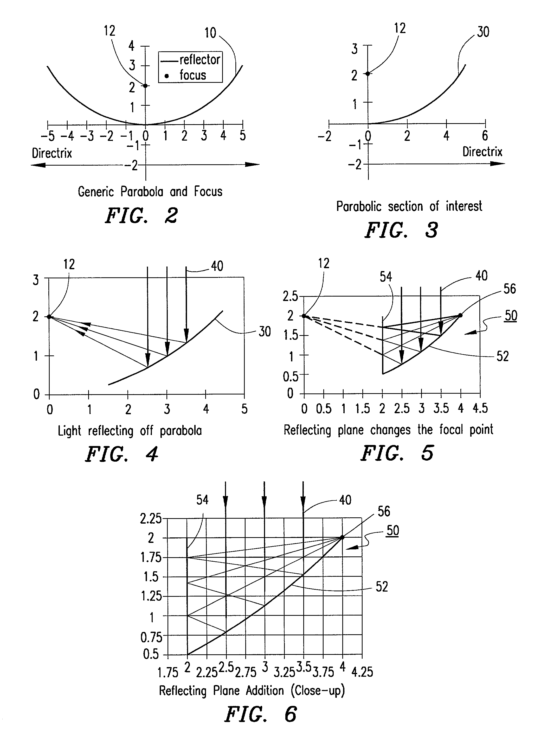
[0032] The exemplary embodiments provide a double reflecting solar concentrator which has useful optical and construction properties which lend itself to low construction costs, installation costs, and operational costs.

[0033] The exemplary concentrators geometrically comprise a predetermined portion of a parabolic mirror in combination with a planar mirror that allows light to be focused on and along a predetermined portion of the surface of the parabolic mirror, or alternately along a predetermined portion of the surface of the planar mirror.

[0034] FIG. 2 depicts a traditional generic parabolic shape 10 and focal point 12. A parabola is the set of points, in a plane that are equidistant from a focus point and a line in the plane (the line is sometimes called a directrix). The exemplary embodiments of the present invention utilize a portion of the parabolic arc 10. It is understood that virtually any parabolic arc (parabolic equation) can be utilized in the present invention. FIG. ...


PUM


Abstract

A double reflecting solar concentrator utilizing a primary reflective surface which reflects incident light toward a secondary surface. The incident light reflects off the secondary surface away from the primary surface's natural focus point toward a secondary focal point positioned on or substantially near the surface of the primary reflective surface.

Description

[0001] This application is a continuation in-part of co-pending application Ser. No. 09 / 579,537 filed on May 24, 2000, which is hereby incorporated by reference as if reproduced herein.[0002] 1. Technical Field of the Invention[0003] The present invention relates to solar concentrators and solar collector systems. More particularly, the present invention relates to a linear solar concentrator which utilizes a portion of a parabolic arc or a planar surface for a first reflection surface and a planar or a parabolic secondary reflection surface for concentrating solar energy in a substantially linear fashion on a predetermined portion of the first reflection surface.[0004] 2. Description of Related Art[0005] Solar concentrators work by collecting sunlight from a large area and concentrating sunlight into a smaller area. There are identifiable techniques for converting solar energy into useable forms, but whether or not the solar energy is collected and converted on a substantial scale ...

Claims


Application Information

Patent Timeline
Patent Type & Authority Applications(United States)
IPC IPC(8): F24J2/50F24J2/54F24S23/70F24S23/71F24S23/74F24S23/77F24S23/79F24S50/20H01L31/042
CPCF24J2/1047F24J2/14F24J2/16F24J2/18F24J2/541F24J2/5417Y02E10/45Y02E10/47Y02E10/52F24S23/74F24S23/77F24S23/79F24S23/80F24S30/425F24S30/45Y02E10/40
Inventor FRAZIER, SCOTT
Owner FRAZIER SCOTT
Why Eureka
Try Eureka