
Wireless digital launch or firing system

Inactive Publication Date: 2001-11-29
HOLDAWAY CHARLES R +1
View PDF1 Cites 142 Cited by
  • Summary
  • Abstract
  • Description
  • Claims
  • Application Information

AI Technical Summary

Benefits of technology

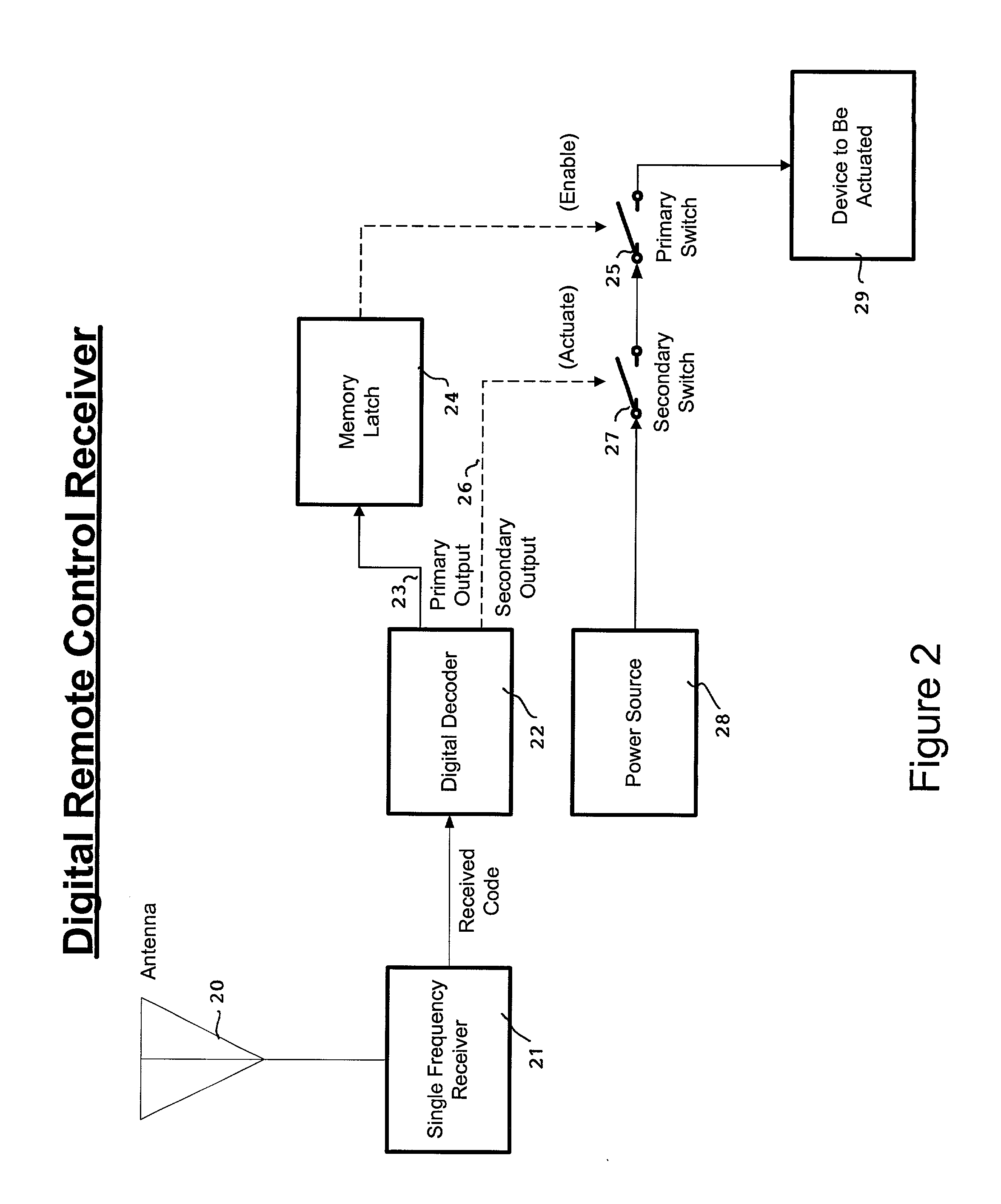
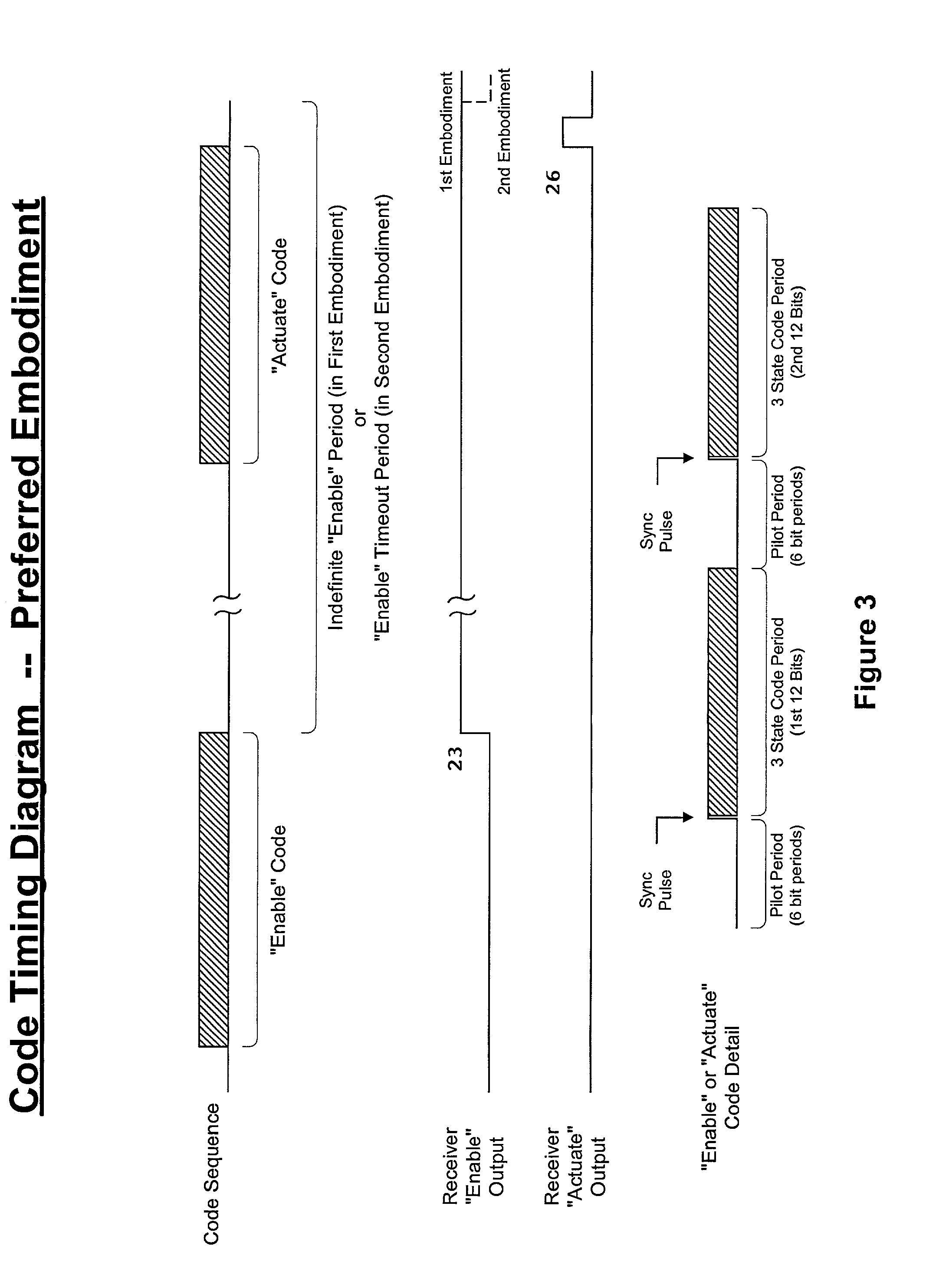
[0013] The system of the invention provides certain advantages and improvements over the prior devices. The use of a digital processor allows the two, or many, different signals of the same frequency or type to be demodulated and compared by the same receiver circuit and processor, thereby providing a simpler configuration and saving on fabrication and assembly costs. This can result in significant savings when the system is used for multiple firings. The memory latch device allows the system to be set to the "enable" condition, thereby avoiding the need to have the operator depress both transmitter switches at the same time. The memory latch device can also be set to the "enable" condition for a timed period, which provides greater safety against inadvertent triggering if the operator or another person decides to approach the launch device after it had been set to the "enable" condition.

Problems solved by technology

The limited bandwidth frequencies assigned by the Federal Communications Commission (FCC) for these devices have become so crowded in use that it is very common for signals from one transmitter device to interfere with another device intended to be operated by its own transmitter.
This presents a serious problem in the use of remote controls for launching of model rockets, actuation of pyrotechnics devices, firing of hazardous explosive devices, and the like.
When such systems are armed for firing, there is an ever present danger that they may be inadvertently set off prematurely by a spurious signal from another remote-controlled device or radio device.
Premature actuations of explosive devices have become unacceptably frequent in recent years, posing a serious threat of injury to explosive ordinance technicians, stagehands, actors, and spectators, as well as ruining the intended performance.
However, the above-described system has the problem that the operator must depress two switches simultaneously in order to actuate the remote-controlled device.
This is particularly inconvenient in the case of large pyrotechnic displays that have many hundreds of launchers, and it is desired that the launchers be readied for firing beforehand and actuated with split-second timing in a complex timed sequence.

Method used


Image

  • Wireless digital launch or firing system
  • Wireless digital launch or firing system
  • Wireless digital launch or firing system

Examples


Embodiment Construction

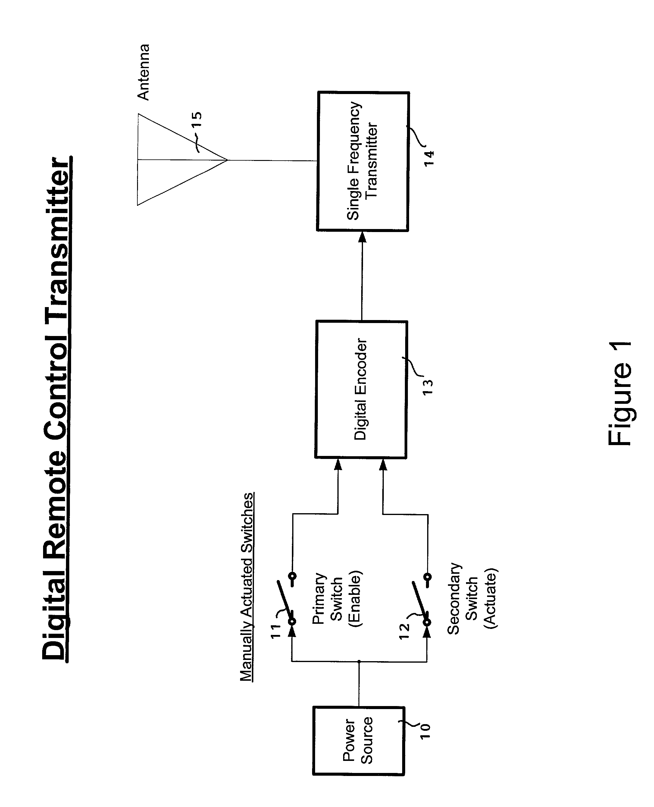
[0023] Referring to FIG. 1, a transmitter unit for a wireless digital launch or firing system in accordance with the invention is shown schematically having a power source 10, such as a battery, a primary (Enable) switch 11, a secondary (Actuate) switch 12, a digital encoder 13, a single-frequency transmitter 14, and an antenna 15. Closing the Enable switch 11 sends a voltage signal to one input of the digital encoder 13 to generate a first digital code sequence representing a valid Enable signal, which is converted to a corresponding radio-frequency (RF) signal in pulse code form for transmission via antenna 15. The conversion of a digital code signal into pulse code form by AM modulation between carrier On and Off states is well known to those skilled in this field and not described in further detail herein. Similarly, closing the Actuate switch 12 sends a voltage signal to another input of the digital encoder 13 to generate a second digital code sequence representing a valid Actu...


PUM


Abstract

A wireless digital launch or firing system has a transmitter unit that can transmit separate RF signals representing an "enable" code sequence and an "actuate" code sequence, and a receiver unit which decodes the "enable" code sequence to enable receipt of the "actuate" code sequence, and decodes the "actuate" code sequence to actuate launching or firing. A digital processor receives the code sequences from a receiver circuit and compares them to stored digital code sequences. A memory latch maintains a normally-off primary switch in an "on" condition when the "enable" signal is received. A normally-off secondary switch is set to an "on" condition when the "actuate" signal is received. Preferably, the RF signals are transmitted in pulse code form, and the code sequences include bits that are predetermined and stored in the hardware, bits that are selected for an individual code by the user, and bits that differentiate the "enable" from the "actuate" signal. The memory latch can be set to an indefinite "enable" period, for multiple launchings, or a timed "enable" period, for toys or single launch devices. A sequencer module can be coupled to the receiver unit for sequenced firings.

Description

SPECIFICATION[0001] This U.S. patent application claims the priority of U.S. Provisional Application No. 60 / 194,188 of the same inventors, filed on Apr. 3, 2000, entitled "Wireless Digital Launch or Firing System for Model Rockets, Pyrotechnic or Hazardous Explosive Devices.[0002] This invention generally relates to a launch or firing system, and more particularly, to a system employing wireless digital circuitry for improved operation.BACKGROUND OF INVENTION[0003] Many different types of radio-controlled and remote-controlled devices are commonly used for cellular telephones, portable phones, wireless PDAs, short range radio communicators, toys, remote monitors, pagers, garage door openers, etc. The limited bandwidth frequencies assigned by the Federal Communications Commission (FCC) for these devices have become so crowded in use that it is very common for signals from one transmitter device to interfere with another device intended to be operated by its own transmitter. This pres...

Claims


Application Information

Patent Timeline
IPC IPC(8): H04B1/04
CPCH04B1/04
Inventor HOLDAWAY, CHARLES R.TUCKER, CHARLES J. JR.
Owner HOLDAWAY CHARLES R
Learn More