Electric toothbrush

a toothbrush and electric technology, applied in the field of electric toothbrushes, can solve the problems of increasing complexity, increasing the cost of motorized motion, and reducing the use of electric toothbrushes, and achieving the effect of facilitating easy manufacturing, and easy access to the back of the user's mouth

Inactive Publication Date: 2001-12-27
CHURCH & DWIGHT CO INC
View PDF0 Cites 29 Cited by
  • Summary
  • Abstract
  • Description
  • Claims
  • Application Information

AI Technical Summary

Benefits of technology

0009] One advantage of the present invention is the provision of an electric toothbrush with a switch which allows momentary operation of the toothbrush while the toothbrush is inside sealed factory packaging.
0010] Another advantage of the present invention is the provision of an electric toothbrush which is inexpensive and easy to manufacture.
0011] Still another advantage of the present invention is the provision of an electric toothbrush with moving portion that rotates, swivels, oscillates or reciprocates.
0012] Yet another advantage of the present invention is the provision of a circular portion that rotates, reciprocates, swivels, or oscillates which is positioned at the end of the brush head to facilitate easier access to the back of the user's mouth.
0013] Still other advantages and benefits of the invention will become apparent to those skilled in the art upon a reading and understanding of the following detailed description.

Problems solved by technology

However, an examination of the available technology shows a tendency toward increasingly complex, expensive, and non-commercially feasible methods of achieving motorized motions in the bristles and heads of toothbrushes to aid in more effectively cleaning one's teeth.
The lower end of the market has become the province of very simple motorized toothbrushes that only vibrate through the use of an offset weight attached to the motor shaft, and which provide very little true additional cleaning benefit with their use, since no vigorous motion is transmitted to the cleaning surface of the brush.
The vibrations are also very uncomfortable to the hand and act as a disincentive to brush one's teeth for an adequate time.
None of these toothbrushes provides a low cost / hygienic means for a customer to try the toothbrush before making a toothbrush purchase.

Method used


Image

  • Electric toothbrush
  • Electric toothbrush
  • Electric toothbrush

Examples


Embodiment Construction

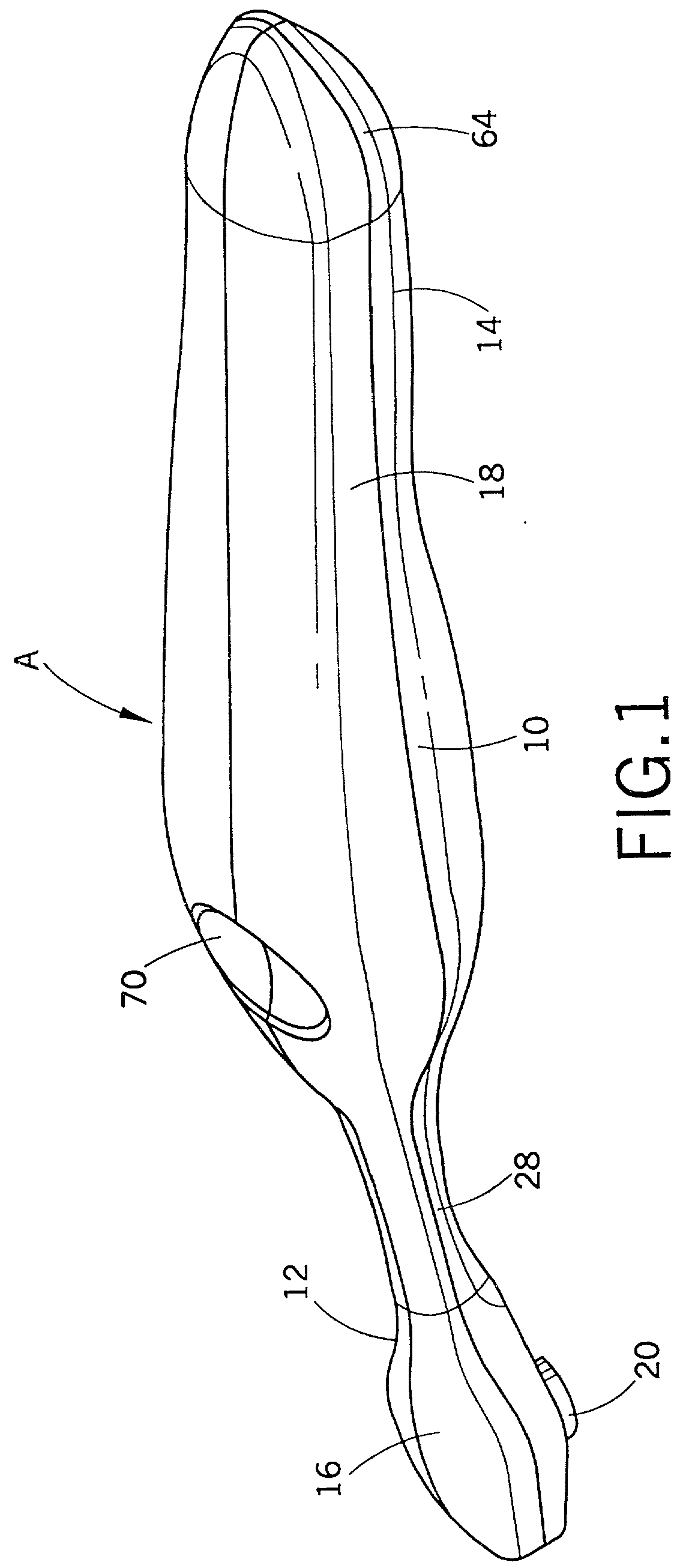
[0023] Referring now to the drawings wherein the showings are for the purposes of illustrating the preferred embodiments of the invention only and not for purposes of limiting same, FIG. 1 shows an first electric toothbrush A. The electric toothbrush can be used for personal hygiene such as brushing one's teeth and gums.

[0024] As shown in FIG. 1, the electric toothbrush includes an body portion 10, which has a first end 12 and a second end 14. A head 16 is located at the first end 12 and a handle 18 is located at the second end 14.

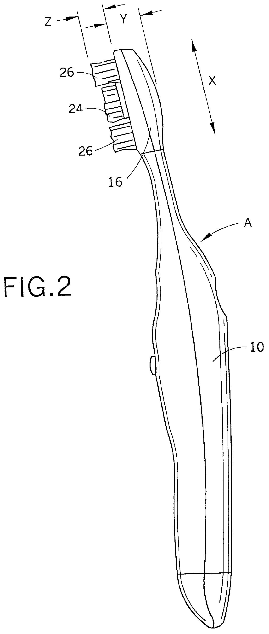
[0025] The exemplary head 16 has a more traditional larger brush head shape which permits the user to brush his teeth in the typical manner of an up and down fashion. As shown on FIG. 2, the length of the head 16, dimension "X", can range from about 0.75 inches to about 1.75 inches. The thickness of the brush head, dimension "Y", can range from about .25 inches to about 0.50 inches. The design of the head 16 allows for inexpensive manufacture and assists i...


PUM


Abstract

An electric toothbrush includes a head having a moving portion, a handle, and shaft between the head and the handle. An body portion is hollow and further includes a motor operative to generate motion for driving the moving portion. A battery is located within the hollow section for powering the motor. A First switch, operatively connected to the motor provides momentary operation of the toothbrush. Optionally, a second switch provides for continuous operation of the toothbrush. The first switch can be operated while the toothbrush is in a toothbrush package, such as, for example, a plastic blister pack. A consumer can momentarily observe the operation of the toothbrush before purchasing the toothbrush. The consumer cannot operate the second switch and is thereby prevented from leaving the toothbrush in a battery draining operational mode for extended periods of time.

Description

[0001] This application is a continuation-in-part of application Ser. No. 09 / 710,616, filed on Nov. 9, 2000, which is a continuation-in-part of Application Ser. No. 09 / 382,745, filed on Aug. 25, 1999, which issued as U.S. Pat. No. 6,178,579 on Jan. 30, 2001, and which is a continuation-in-part of Application Ser. No. 09 / 236,794, filed Jan. 25, 1999, which issued as U.S. Pat. No. 6,189,693 on Feb. 20, 2001, and which is a continuation-in-part of application Ser. No. 09 / 163,621, filed on Sep. 30, 1998, which issued as U.S. Pat. No. 6,000,983 on Dec. 14, 1999.BACKGROUND OF THE INVENTION[0002] The present invention relates generally to electric toothbrushes. More particularly, it relates to an improved battery powered toothbrush.[0003] The benefits of brushing one's teeth using motorized toothbrushes are well known, and motorized movement in toothbrushes has been the subject of much recent innovation and design activity. Also, the commercial market has seen the introduction, over the la...

Claims


Application Information

Patent Timeline
Patent Type & Authority Applications(United States)
IPC IPC(8): A61C17/22A61C17/26A61C17/34
CPCA61C17/22A61C17/221A61C17/26B29L2031/425A61C17/3436A61C17/349A61C19/02A61C17/34A61C2204/002
Inventor BLAUSTEIN, LAWRENCE A.NOTTINGHAM, JOHN R.OSHER, JOHNSPIRK, JOHN W.GALL, DOUGLAS A.
Owner CHURCH & DWIGHT CO INC
Why Eureka
Try Eureka