Flexible coaxial cable and a method of manufacturing it

Inactive Publication Date: 2002-01-10
NEXANS
View PDF0 Cites 19 Cited by
  • Summary
  • Abstract
  • Description
  • Claims
  • Application Information

AI Technical Summary

Benefits of technology

0008] An object of the present invention is to provide a flexible coaxial cable having a shield of reliable structure leading to pe

Problems solved by technology

Nevertheless, the turns themselves tend to move during such bending/straightening of the cable, thereby changing the contact resistance and the assembly configuration of the turns relative to one another and relative to the inner tape, leading to current flowing along a helical path in the outer tape and thus limiting the performance of the shield.
While the molten metal is being applied, the tape acts as a thermal shield so as to isolate the insulation thermally from the molten metal, given that in the absence of the tape, the molten metal would come directly into contact with the insulation and could harm it.
Nevertheless, the layer of metal between the braid and the

Method used


Image

  • Flexible coaxial cable and a method of manufacturing it
  • Flexible coaxial cable and a method of manufacturing it

Examples


Example

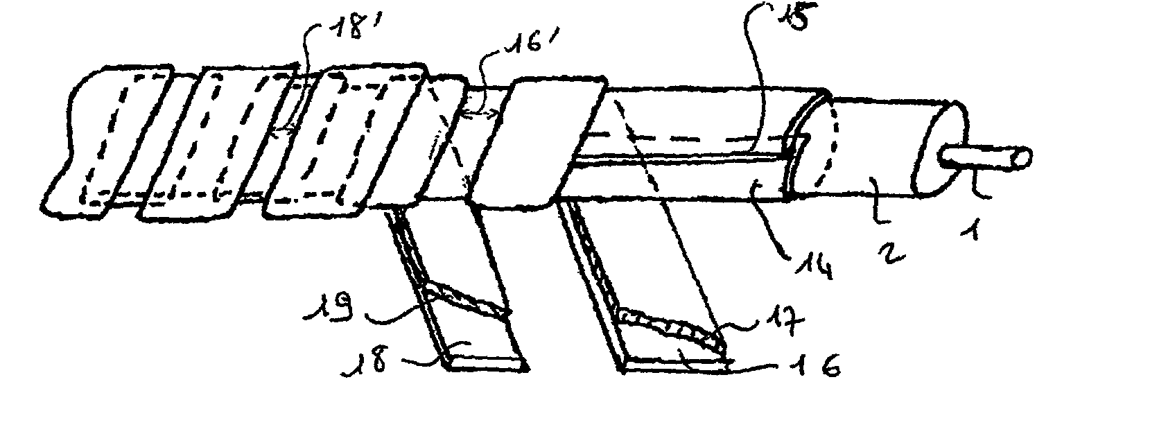
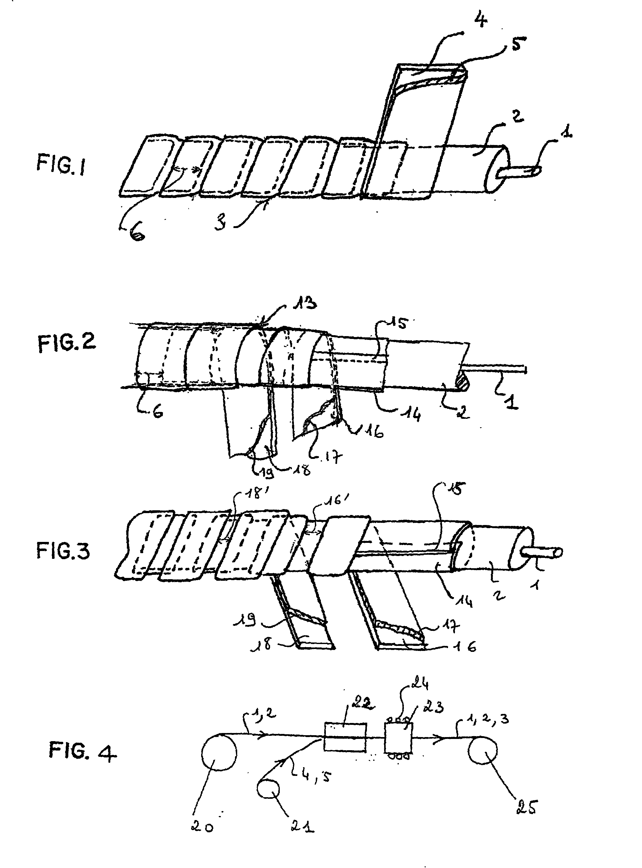
[0021] With reference to FIG. 1, the cable comprises a flexible conductive core 1, flexible insulation 2 covering said core, and a flexible shield 3 surrounding said insulation.

[0022] The flexible shield 3 is constituted by a metal tape 4 which is provided with a metal coating 5 at least on its outside face, which is wound helically around the insulation, with turns that overlap widely, and which is sealed onto itself in leakproof manner by said coating bonding said turns to one another throughout their overlap zones.

[0023] The overlap referenced 6 between the turns is shown as being 50%. In practice, it can be less than that but it must nevertheless be not less than 20% to 25% and is preferably about 40%. It defines an overlap zone that is bonded together without any additional material being supplied, which zone is helical and continuous along the cable so as to provide good sealing and conservation of the performance of the shield 3 made in this way.

[0024] In the cable, the condu...


PUM


Abstract

The flexible coaxial cable comprises a shield formed by at least one metal tape provided with a metal coating and wound helically around the insulated core of the cable. The shield is sealed to itself in leakproof manner by said coating which is melted so as to bond directly together the overlapping turns of a single tape or the overlapping turns of two superposed tapes by subjecting the cable provided with said shield to peripheral induction heating.

Description

[0001] The present invention relates to flexible coaxial cables and more particularly to such cables of small section suitable for use in particular in medical imaging, or in portable transmission equipment such as computers, or for conveying microwaves.[0002] One of the requirements that needs to be satisfied is that the outer conductor or shield of such a cable must remain fully effective even though the cable, and thus the shield, are flexible.[0003] Document GB-A-2 130 430 discloses a flexible coaxial cable which has a flexible conductive core, flexible insulation around said core, a conductive shield that is likewise flexible around said insulation, and an optional flexible outer protective sheath. The shield of the cable is constituted by an inner metal tape which is folded longitudinally around the insulation, an outer metal tape which is wound helically around the inner tape, and an optional metal braid, which is then mounted around the outer tape and is designed to enable c...

Claims


Application Information

Patent Timeline
IPC IPC(8): H01B11/18
CPCH01B11/183
Inventor CLOUET, PASCALGUINOT, JEAN-FRANCOISMAISSEU, JEAN-JACQUESVAILLE, FRANCOIS
Owner NEXANS
Why Eureka
Try Eureka