Abrasive polishing apparatus

a technology of abrasive polishing and abrasive polishing, which is applied in the direction of superfinishing machines, other chemical processes, manufacturing tools, etc., can solve the problems of limited operation in some contexts, increasing the complexity of equipment and the time and effort required to change work pieces

Inactive Publication Date: 2002-01-24
EXTRUDE HONE CORP
View PDF0 Cites 4 Cited by
  • Summary
  • Abstract
  • Description
  • Claims
  • Application Information

AI Technical Summary

Benefits of technology

[0016] It is an object of the present invention to provide an improved abrasive machining process and apparatus in which a gap is maintained during the processing between the visco-elastic medium and portions of the work piece.
[0017] It is another object of the present invention to provide an improved abrasive machining process and apparatus employing a visco-elastic abrasive medium which conforms to the shape and conformation of each work piece.

Problems solved by technology

Such operations have been limited in some contexts, however, by several factors.
Such flow does an excellent job of polishing surfaces at high speed, but for more demanding operations involving significant removal of stock from the work piece, the operation is typically slow.
Second, the chamber in which the orbital working takes place must be closed or sealed to confine the medium within the chamber, assuring adequate strain rates are attained and imparted to the medium to provide the required work, adding to the complexity of the equipment and the time and effort required to change work pieces.
These requirements also contribute substantially to the cost of the process and equipment and may, in some cases, be a limiting factor determining the rate of production.

Method used


Image

  • Abrasive polishing apparatus
  • Abrasive polishing apparatus
  • Abrasive polishing apparatus

Examples


example 2

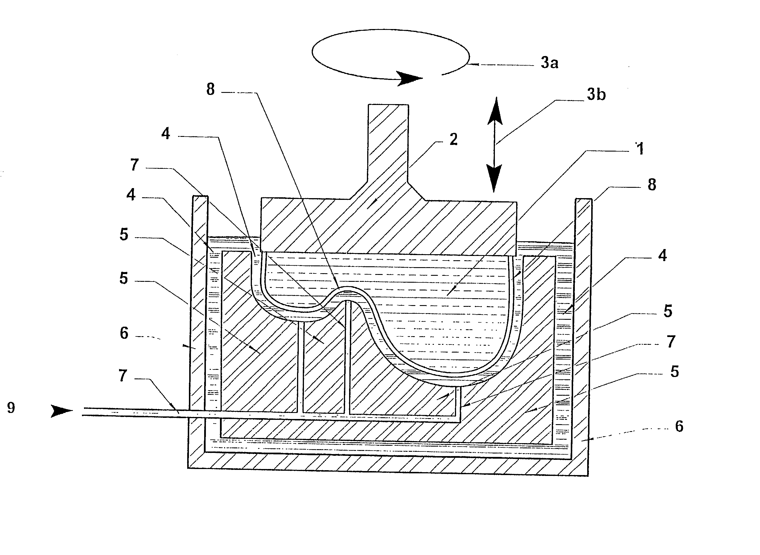
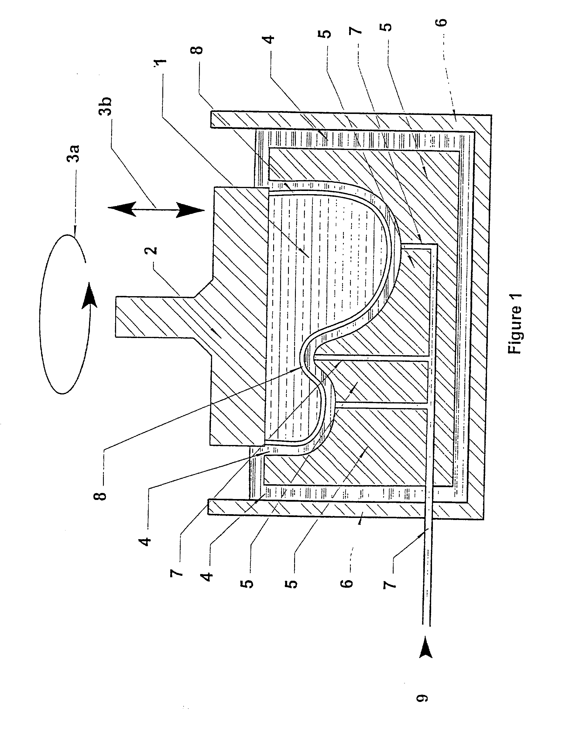
[0169] The apparatus illustrated in FIG. 1 was also employed to polish a plurality of forged aluminum components of having a three-dimensionally complex shape. The components as received had a surface roughness of 100 to 120 micro-inches R.sub.a . The apparatus was fitted with a displacer shaped as a complement of the shape of the components and providing a gap of 6 millimeters. The surface of the wheels were polished for 3.5 minutes, employing an orbit of 0.25 inches at a frequency of 17 Hz, employing poly(boro-siloxane) media and a 80 mesh abrasive, followed by a second polishing of 2 minutes, employing an orbit of 0.25 inches at a frequency of 17 Hz, employing poly(boro-siloxane) media and a 220 mesh abrasive. The surfaces of the wheels were measured to have a surface roughness ranging from 20 to 25 micro-inches R.sub.a as finished.

example 3

[0170] The apparatus illustrated in FIG. 1 was also employed to polish a plurality of cast aluminum a automotive wheels having a complex shape. The wheels as received had a surface roughness of 140 to 175 micro-inches R.sup.a. The apparatus was fitted with a displacer shaped as a complement of the shape of the wheels and providing a gap of 6 millimeters. The surface of the wheels were polished for 3.5 minutes, employing an orbit of 0.25 inches at a frequency of 17 Hz, employing poly(boro-siloxane) media and a 80 mesh abrasive, followed by a second polishing for 1.5 minutes, employing an orbit of 0.25 inches at a frequency of 17 Hz, employing poly(boro-siloxane) media and a 220 mesh abrasive. The surfaces of the wheels were measured to have a surface roughness ranging from 20 to 25 micro-inches R.sub.a as finished

[0171] The invention has been described herein with regard to particular preferred operating circumstances and requirements, and in a particular context. Those of ordinary s...


PUM

PropertyMeasurementUnit
frequencyaaaaaaaaaa
frequencyaaaaaaaaaa
SURFACE ROUGHNESSaaaaaaaaaa

Abstract

The present invention is based on the practice of abrasive machining with no sealed working chamber by the employment of a visco-elastic abrasive medium, behaving predominantly as an elastic solid at the applied strain of the orbital working motion, and applying orbital or other relative working motion to produce strain rates which bring the medium into a predominantly elastic deformation and often near, but not to exceed, the compressive stress limit at the strain rate employed. The preferred visco-elastic abrasive medium is a rheopectic poly(boro-siloxane) filled with viscosity increasing stiffening agents and high loadings of the abrasive of choice and relatively minor amounts of plasticizers. The system is operated in an open chamber under applied strain rates such that at least about 50%, particularly about to 99%, and preferably about 80 to 95%, of the deflection of the medium tinder the conditions of operation occurs by elastic deformation and is elastically recovered, and less than 50%, particularly about 1 to 50%, preferably about 5 to 20%, of the deflection of the medium occurs by fluid or plastic flow.

Description

[0001] This application is a continuation in part of U.S. Pat. application, Ser. No. 09 / 139,642 filed Aug. 26, 1998.[0002] The present invention relates to apparatus and methods for performing abrasive work on a work piece using a visco-elastic medium and, in particular, to apparatus and methods that imparts a relative cyclic motion between the work piece and the abrasive to provide a gap between the medium and work piece during each cycle which gap comprises a fluid having a viscosity less than the visco-elastic medium and where the deformation of the medium is between 50 and 99%.[0003] 1. Technical Field[0004] The present invention relates to the technical field of machining and particularly to the field of non-traditional machining processes and equipment employing the techniques of and compositions for abrasive flow machining, grinding, deburring, radiussing, leveling and polishing of work pieces. Such processes are typically employed in the working of castings, forged parts, ma...

Claims


Application Information

Patent Timeline
Patent Type & Authority Applications(United States)
IPC IPC(8): B24B31/116B24B35/00C09C1/68C09K3/14
CPCB24B31/116B24B35/005C09K3/14B24B1/00C09G1/02
Inventor GILMORE, JAMES RANDALLRHOADES, LAWRENCE J.
Owner EXTRUDE HONE CORP
Why Eureka
Try Eureka