Optical filter and plasma display panel

Inactive Publication Date: 2002-02-14
BRIDGESTONE CORP
View PDF0 Cites 23 Cited by
  • Summary
  • Abstract
  • Description
  • Claims
  • Application Information

AI Technical Summary

Benefits of technology

0008] It is an object of the present invention to solve conventional problems as above and to provide an optical filter which can correct the emission spectrum of

Problems solved by technology

Although the PDP is usually mounted with a filter to block near infrared rays or electromagnetic waves in the front, no filter has served to correct the emission spectrums of the PDP so far.
Light having a wavelength of about 590 nm is almost orange in c

Method used


Image

  • Optical filter and plasma display panel
  • Optical filter and plasma display panel
  • Optical filter and plasma display panel

Examples


example 2

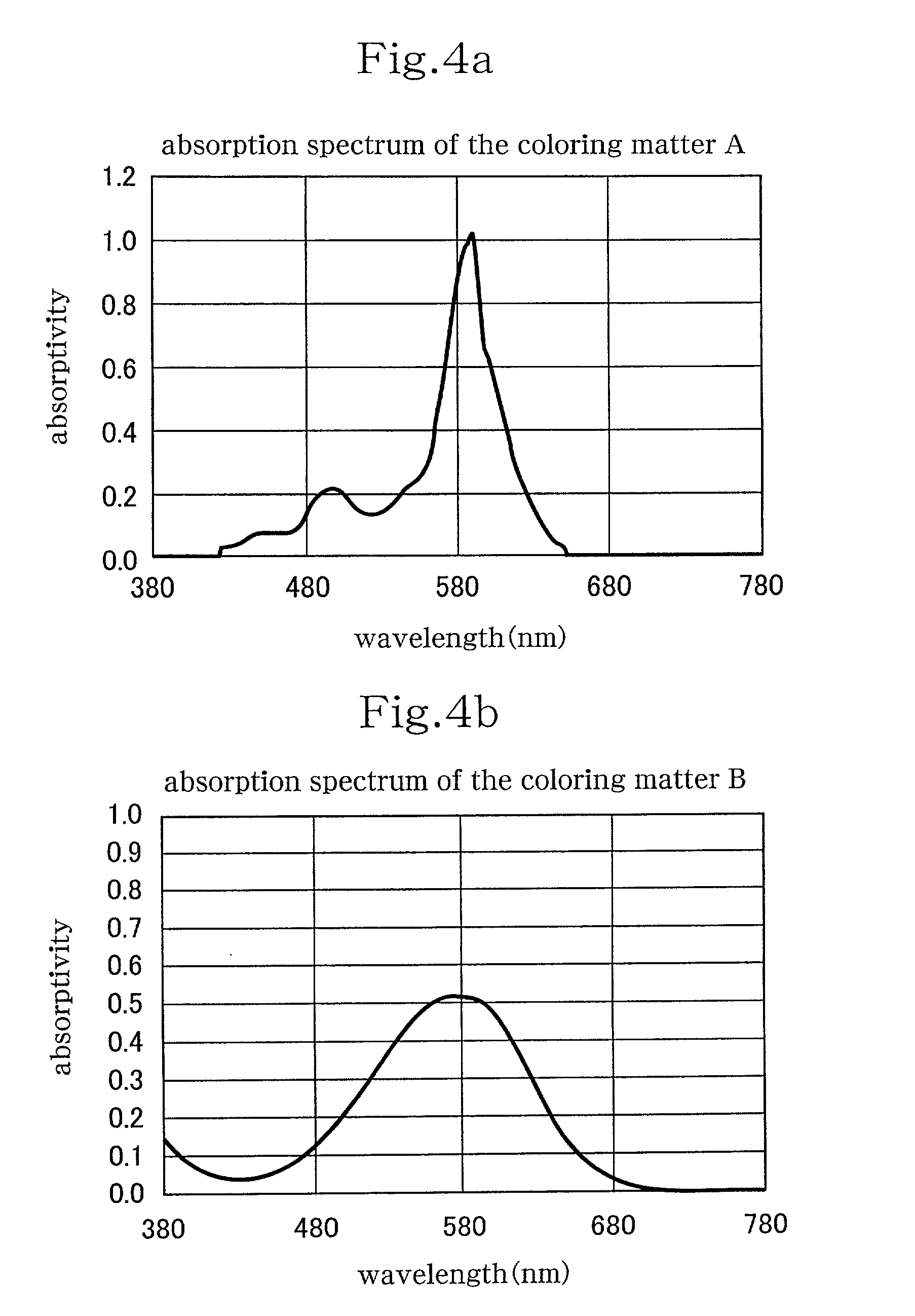
[0032] A methacrylic resin (PMMA) and the dyestuff A employed in the above Example 1 were dissolved in a solution composed principally of tetrahydrofuran. The solution was, then, applied uniformly onto a polyester film having a thickness of 100 .mu.m and dried to form a 5 .mu.m thick film including the dyestuff A.

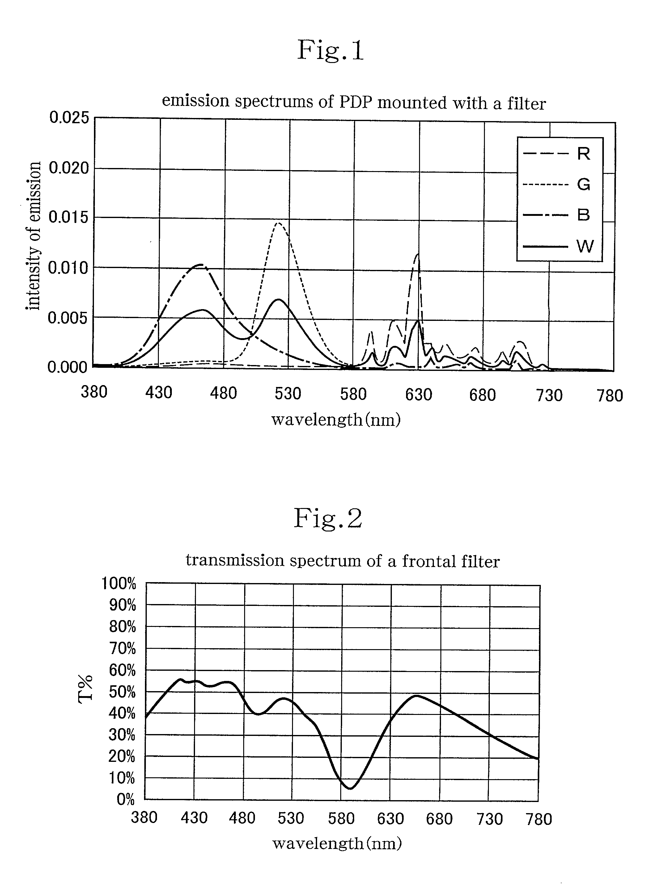
[0033] This film includes the dyestuff A of 0.13 g / m.sup.2. It was shown that this film has about the same transmission spectrum as that of the PDP filter of Example 1.

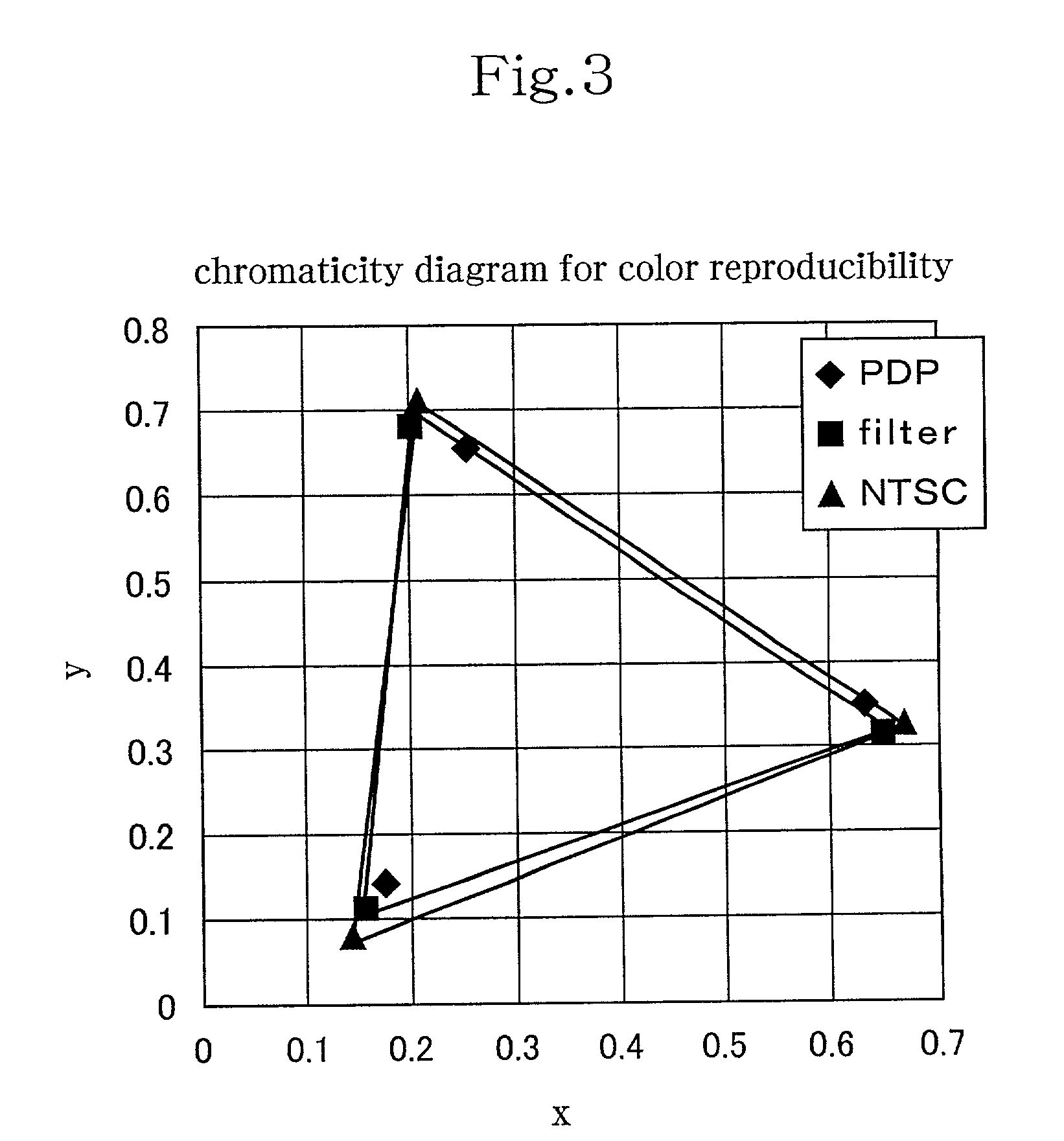
[0034] This filter was mounted in the front of the PDP to measure the plain-color emission spectrums of red light, green light and blue light, respectively, and the chromaticity coordinates. The results show that the range of the color reproducibility of the film also approaches the ideal range of the color reproducibility of the emission devices of the PDP.


PUM

PropertyMeasurementUnit
Widthaaaaaaaaaa
Wavelengthaaaaaaaaaa

Abstract

An optical filter includes a coloring matter which has an absorption peak in a wavelength range of 570 to 600nm. The optical filter is mounted in the front of a PDP. The spectrums of the PDP shall be corrected by the filter, so that the PDP can be improved in color purity and color reproducibility.

Description

[0001] This is a continuation application of PCT / JP01 / 00747 filed on Feb.2, 2001.[0002] The present invention relates to an optical filter, such as an electromagnetic-wave shielding light-transparent plate which is mounted in the front of a plasma display panel (hereinafter, the plasma display panel will be referred to as the "PDP" and the electromagnetic-wave shielding light-transparent plate for the PDP will be referred to as a "PDP filter."), and a PDP which is mounted with the filter in the front thereof.[0003] The PDP displays colors by emitting plasma having different emission spectrums, or by controlling the degrees of emission of red light (R), green light (G), blue light (B), and white light (W), which is developed by total emission of those three colors of light, respectively as shown in FIGS. 5a through 5d.[0004] Although the PDP is usually mounted with a filter to block near infrared rays or electromagnetic waves in the front, no filter has served to correct the emission...

Claims


Application Information

Patent Timeline
IPC IPC(8): C09J11/06G02B5/22H01J11/44
CPCG02B5/223Y10T428/28H01J11/44Y10T442/10Y10T442/109Y10T442/172
Inventor SUGIMACHI, MASATO
Owner BRIDGESTONE CORP
Why Eureka
Try Eureka