
Multiple-wavelength amplified telecommunications system with gain compensation

a multi-wavelength amplified telecommunications and gain compensation technology, applied in the field of multi-wavelength amplified telecommunications systems with gain compensation, can solve the problems of noise figure increase with a decrease in attenuation along the feedback loop, noise figure of these amplifiers increases with a decrease in attenuation, and amplifier variation gain, so as to achieve the effect of reducing the noise figur

Inactive Publication Date: 2002-02-28
CORNING INC
View PDF2 Cites 31 Cited by
  • Summary
  • Abstract
  • Description
  • Claims
  • Application Information

AI Technical Summary

Benefits of technology

0229] The laser effect is present when:
0230] G / A.sub.loop=1, where A.sub.loop is the loop attenuation (or loss);
0231] therefore e.sup.[(g*+.alpha.)n.sup..sub.2.sup.-.alpha.].cndot.L / A.s-ub.loop=1,
0232] and consequently 1 n _ 2 = ( g * + ) + 10 log A loop 10 L log e ( g * + ) , and, also taking into account the background loss : n _ 2 = +( g * + ) + 10 log A loop4.34 L ( g * + ) ,
0233] {overscore (n)}.sub.2 can be used to determine, in addition to the gain G, the noise figure NF=2{overscore (n)}.sub.sp, where the inversion factor {overscore (n)}.sub.sp is given by: 2 n _ sp =N 2N 2 - N 1= n _ 2 n _ 2 - n _ 1= n _ 22n _ 2 - 1 .
0234] It should be noted that when the loop loss A.sub.loop is increased the noise figure NF decreases.

Problems solved by technology

The applicant has observed that, in amplifiers with gain stabilized by a feedback loop according to the prior art, the stabilization is achieved at the cost of a significant increase in the noise figure.
In particular, the applicant has observed that the noise figure of these amplifiers increases with a decrease in the attenuation along the feedback loop.
In particular conditions, for example in the presence of random switching on and off of one or more of the sources, and consequently in the presence of a variable number of channels supplied simultaneously to the line and to the amplifiers, there are variations of the optical power value between the amplifiers, which may result in variations of gain of the amplifiers such that the quality of the transmission is degraded.
This device is cheaper but is less desirable in terms of signal attenuation.
When the absent channels are reconnected, their amplification in the active fibre consumes the available pump power, and this correspondingly results in a reduction of the level of ASE fed back in the loop.

Method used


Image

  • Multiple-wavelength amplified telecommunications system with gain compensation
  • Multiple-wavelength amplified telecommunications system with gain compensation
  • Multiple-wavelength amplified telecommunications system with gain compensation

Examples


example 2

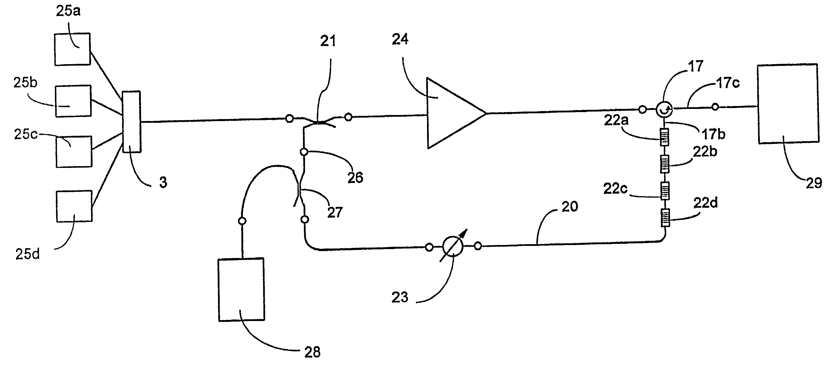
[0216] In order to evaluate the performance of the amplifier according to the invention, a comparison experimental structure was produced with the configuration shown in FIG. 11, in which an interference filter 30 was used in place of the selective filters 22a, 22b, 22c and 22d of the structure shown in FIG. 5, and the feedback loop was connected to the output of the amplification unit 24 by means of a directional coupler 31 of the 50 / 50 type.

[0217] Two tunable band-pass interference filters, made by JDS and having the following characteristics, were tested.

4 Filter 1: Bandwidth at -3 dB BW1.sub.(-3 dB) 3.3 nm Bandwidth at -20 dB BW1.sub.(-20 dB) 11.4 nm; Filter 2: Bandwidth at -3 dB BW2.sub.(-3 db) 1.6 nm Bandwidth at -20 dB BW1.sub.(-20 db) 5.5 nm.

[0218] The feedback loop was made to oscillate at 1530.8 nm by tuning the interference filter to this wavelength.

[0219] Successive measurements were made with different loop loss values, from 26 to 30 dB.

[0220] The results of the measure...


PUM


Abstract

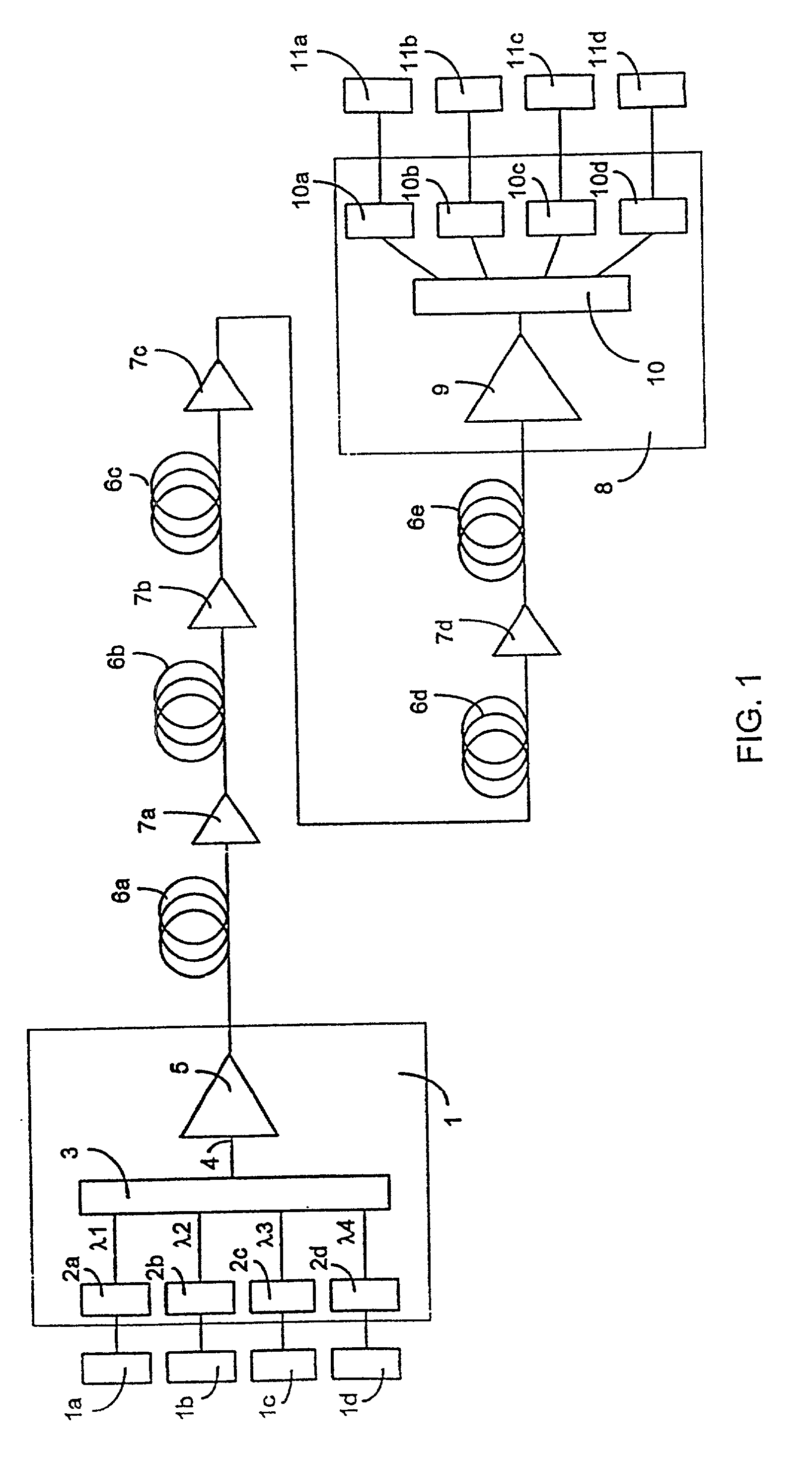
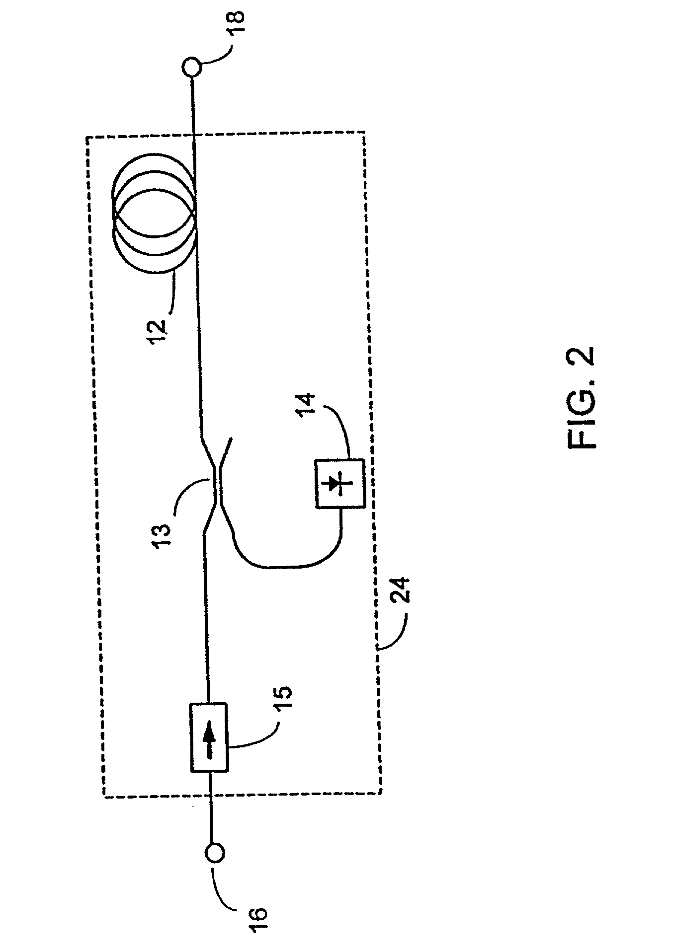
Optical telecommunications system, comprising: a station (1) for transmitting optical signals, comprising a transmission signal generator (2), capable of generating at least two signals at wavelengths lying within a band of predetermined width, and a multiplexer (3) of the optical signals; a station (8) for receiving the optical signals; and an optical fibre line connecting the said multiplexer of the transmission station to the receiving station. The optical fibre line includes at least one optical amplifier (7) comprising at least one fibre (12) doped with a rare earth, at least one source of pumping radiation (14) for the said doped fibre, and a gain stabilization circuit. The gain stabilization circuit comprises: a separator of the transmission signals from the spontaneous emission of the amplifier, connected after the doped fibre and capable of sending the transmission signals to the output of the amplifier and the spontaneous emission to a further output, and a loop circuit for the re-circulation of the said spontaneous emission collected from the said further output and re-injected before the said doped fibre of the amplifier.

Description

[0001] This application claims the benefit of U.S. Provisional patent application No. 60 / 107,389, filed Nov. 6, 1999.[0002] The present invention relates to a telecommunications system including optical amplifiers, particularly suitable for wavelength division multiplexing, or WDM, transmission.TECHNICAL BACKGROUND OF THE INVENTION[0003] For wavelength division multiplexing, or WDM, transmission, it is necessary to send a plurality of transmission signals which are independent of each other along the same line, consisting of optical fibres, by multiplexing in the domain of the optical wavelengths; the transmitted signals may be either digital or analog and are distinguished from each other in that each of them has a specific wavelength, separate from that of the other signals.[0004] The implementation of this WDM transmission requires the allocation of specific wavebands of predetermined width, called "channels" in the following text, to each of the signals having different waveleng...

Claims


Application Information

Patent Timeline
Patent Type & Authority Applications(United States)
IPC IPC(8): H01S3/067H01S3/094H01S3/13H04B10/17H04J14/02
CPCH01S3/06754H01S3/094023H01S3/1302H04B10/296H04J14/0221H04J14/02216
Inventor MELI, FAUSTO
Owner CORNING INC
Learn More