Remote attitude and position indicating system

a position indication and distance technology, applied in direction finders using ultrasonic/sonic/infrasonic waves, instruments, etc., can solve the problems of insufficient tactical consideration of weapons, insufficient positioning of weapons, and inability to accurately determine the position and orientation of objects, so as to reduce the cost impact of environmental design requirements, improve operation and survival, and improve the effect of the effect of the effect of the effect of the effect of the effect of the effect of the effect of the effect of the environmen

Inactive Publication Date: 2002-03-14
HONEYWELL INT INC
View PDF0 Cites 26 Cited by
  • Summary
  • Abstract
  • Description
  • Claims
  • Application Information

AI Technical Summary

Benefits of technology

0020] A primary advantage of the present invention is that the system is minimally obtrusive to the weapons platform
0021] Another advantage of the present invention is since the primary electronics are not on the weapon, the environment is much more friendly, thereby reducing cost impacts of the environmental design requirements on the system
0022] Yet another advantage of the present invention is that the system is extremely ligh

Problems solved by technology

There are several problems with this system/method of laying and subsequent pointing of indirect fire weapons; currently, survey is required to accurately emplace a mortar.
An accurate survey is difficult to transfer to places where indirect fire weapon systems are set up.
Additionally, the time it takes to emplace using an aiming circle is considered too long.
As a result, the weapon is not placed optimally for tactical considerations.
A towed or man portable solution cannot accommodate the

Method used


Image

  • Remote attitude and position indicating system
  • Remote attitude and position indicating system
  • Remote attitude and position indicating system

Examples


Embodiment Construction

)

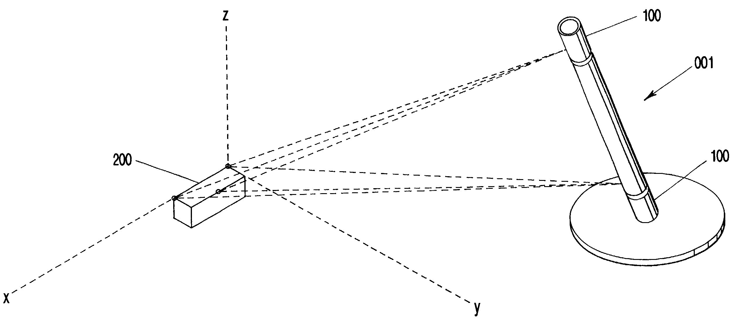
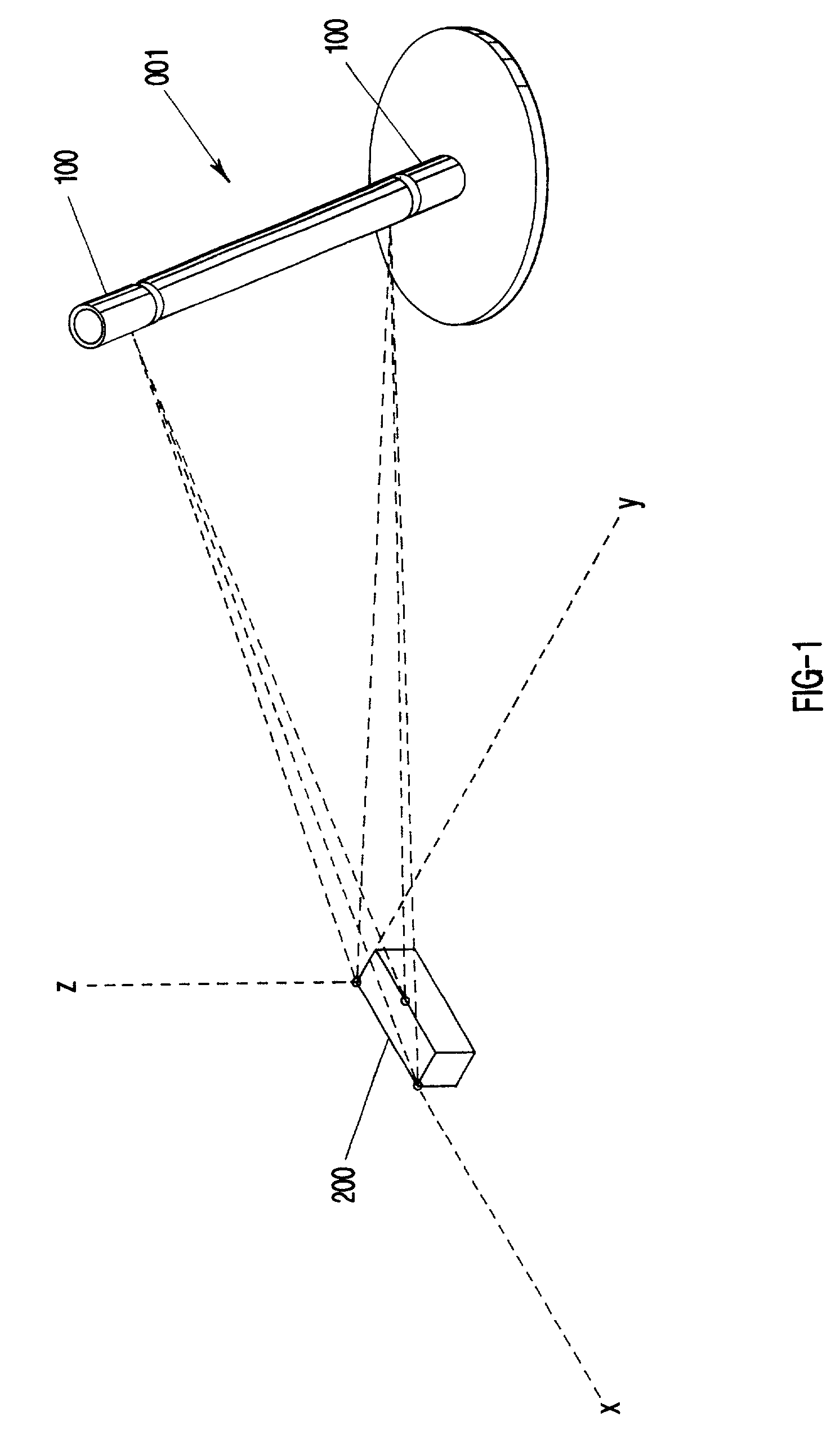
[0032] The present invention comprises a system for determining an arbitrary position and orientation of an object in space without any physical tether or connection to the object and with no alignments or predetermined spatial relationships between the system and the target object. The preferred system is shown in FIG. 1. As shown in FIG. 1, the object of interest 001 represents a mortar tube. This object 001 includes two acoustic emitter assemblies 100 mounted on the axis of the tube and separated by some know distance. The detector box and three associated transducers 200 are located at and establish the reference coordinate system for measurement of the tube attitude. As will be discussed in more detail, the six measured distances between emitter / detector pairs are used to geometrically compute the pointing vector formed by the two emitters on the tube.

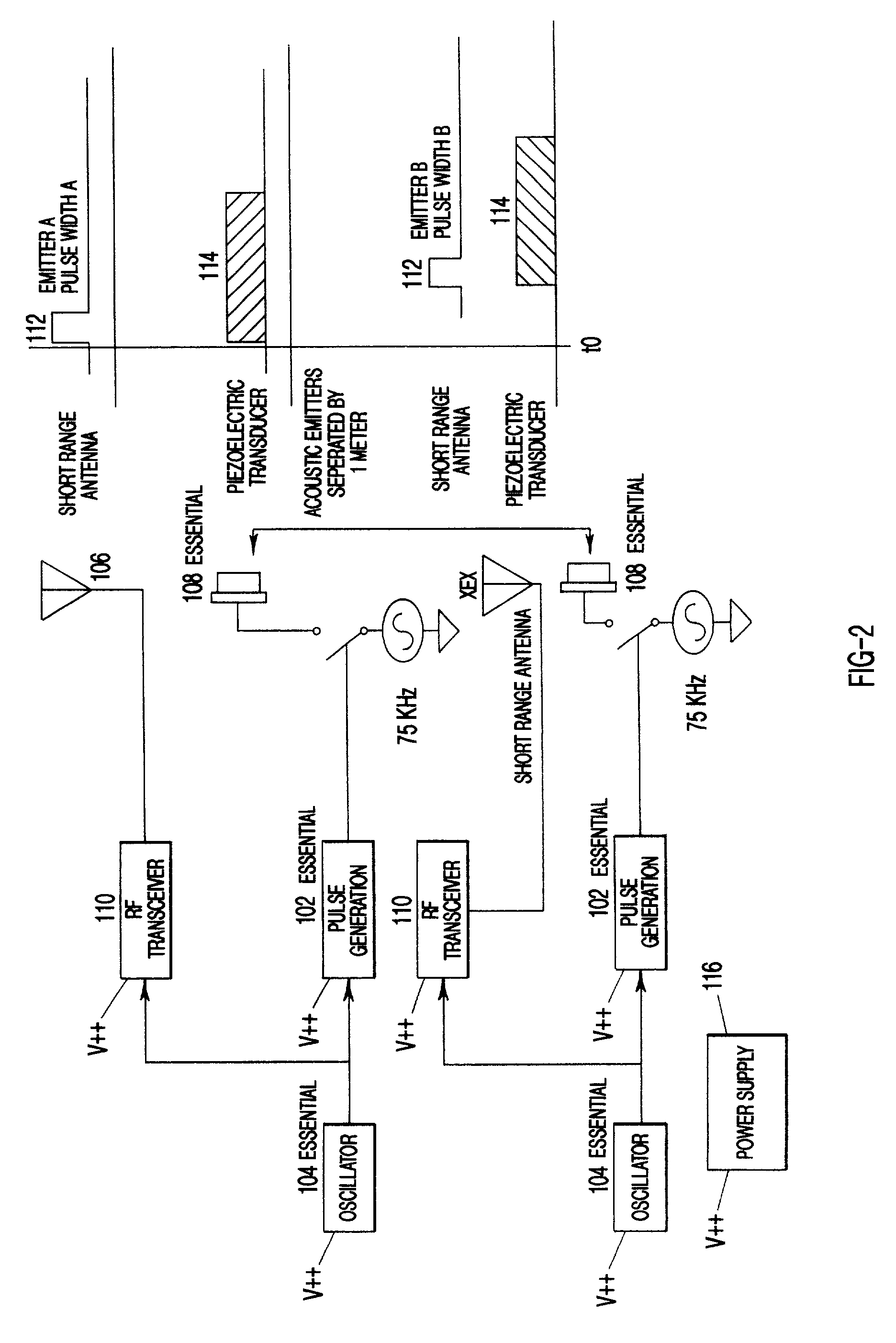
[0033] The system comprises an emitter assembly 100 of FIG. 2 and a detection / processing module 200 of FIG. 3 and associated so...


PUM


Abstract

A method and apparatus using ultrasonic sensors for determination of the pointing vector described by two points separated in space in the coordinate frame of the measuring system. For measurement, acoustic signals are transmitted from two emitters whose spatially separated coordinates form the desired pointing vector. Three detectors, associated receiver electronics and software are required to compute six distinct spheres from the time of flight measurements. The intersection of the three spheres, associated with each emitter, describe the desired location in the detector coordinate system of that emitter. With the coordinates of each emitter, the pointing vector is computed using standard geometry. A reference is required to determine the time of flight of the signals to each detector. Another embodiment uses an active reflective technique, where the timing is obtained through round trip transmission and reception of the signal with a known fixed delay at the vector points.

Description

[0001] This application is based on U.S. Provisional application Ser. No. 60 / 195,925 entitled "Ultrasonic Remote Position and Orientation Sensing System", filed on Apr. 10, 2000, the teachings of which are incorporated herein by reference.[0002] 1. Field of the Invention (Technical Field)[0003] The invention relates to a system for determining the position and orientation of an object and more particularly a method and apparatus for an acoustic based determination of an arbitrary position and orientation of an object in space without any physical tether or connection to the object and with no alignments or predetermined spatial relationships between the system and the target object.[0004] 2. Background Art[0005] The problem that this invention solves is efficient and accurate initial laying of an indirect fire weapon system for location and direction and subsequent attitude measurements necessary to firing the weapon system accurately at a target. Additionally, minimizing weight and...

Claims


Application Information

Patent Timeline
IPC IPC(8): F41G3/16G01S5/30G01S15/08G06F3/033
CPCF41G3/02G06F3/0346Y10S367/907G01S15/06
Inventor BLEVINS, WILLIAM MARKRAKES, LONNYJUDKINS, ERICSCHOESS, JEFFREY NORMAN
Owner HONEYWELL INT INC
Why Eureka
Try Eureka