

Floating connector
a technology of floating connectors and connectors, applied in the direction of incorrect coupling prevention, coupling device connection, printed circuits, etc., can solve the problems of single lateral direction, single lateral direction, and error in another non-lateral single direction that cannot be accommodated, so as to reduce prevent plastic (not elastic) deformation. , the effect of reducing the overall size of floating connectors
- Summary
- Abstract
- Description
- Claims
- Application Information
AI Technical Summary
Benefits of technology
Problems solved by technology
Method used
Image

Examples
first embodiment
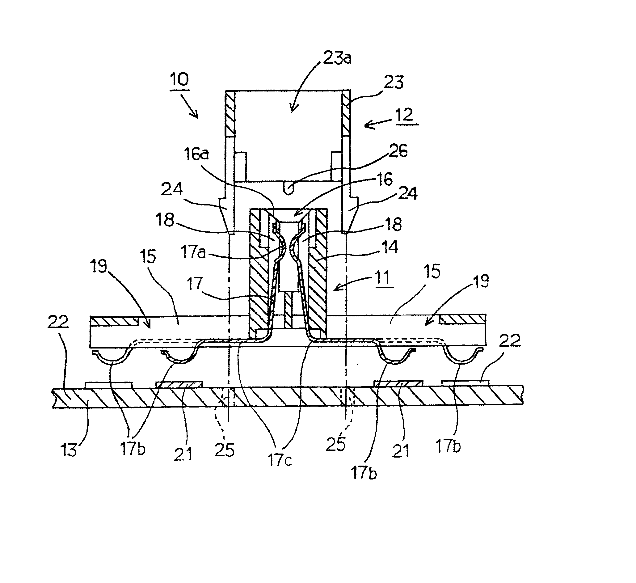
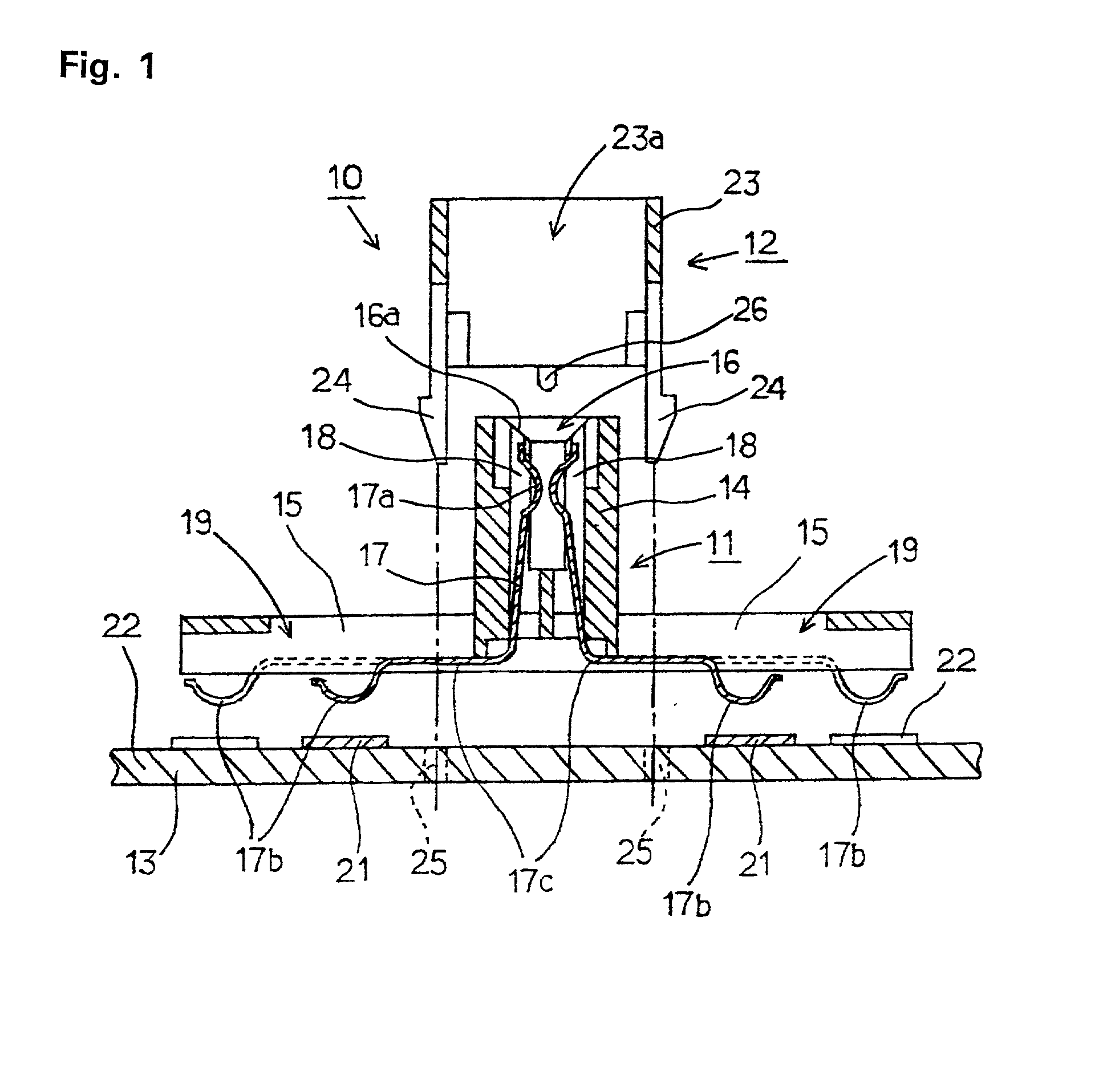
[0055] FIG. 1 is a sectional view of a floating connector according to the present invention.
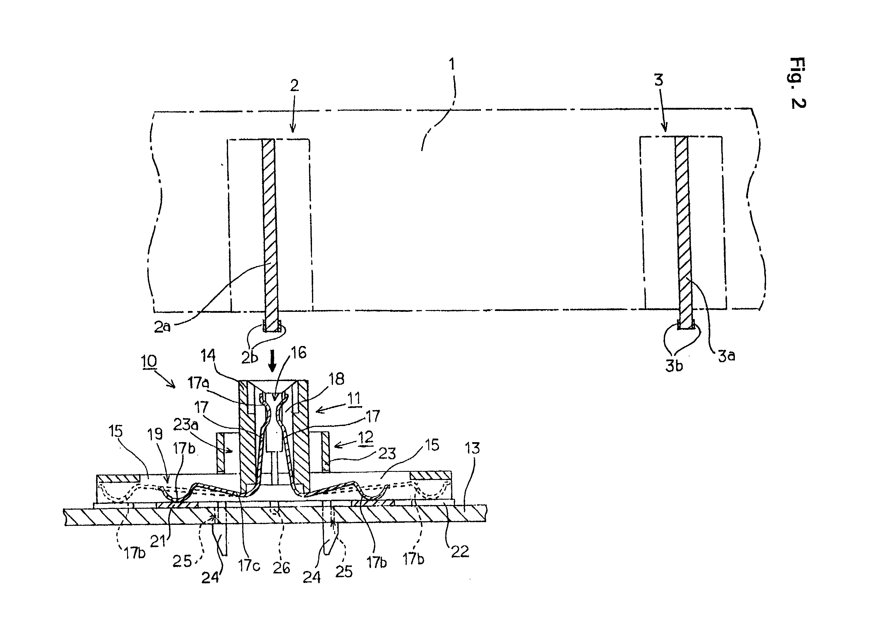
[0056] FIG. 2 is a sectional view of a floating connector connected to an external unit.
[0057] FIG. 3 is a plan view of a floating connector.
[0058] FIG. 4 is a plan view of an insulated housing.
[0059] FIG. 5 is a front view of the insulated housing.
[0060] FIG. 6 is a plan view of a cover.
[0061] FIG. 7 is a front view of the cover.
[0062] FIG. 8 is a partial plan view of a printed circuit board.
second embodiment
[0063] FIG. 9 is a vertical sectional view of a floating connector according to the present invention.
[0064] FIG. 10 is a plan view of the floating connector.
third embodiment
[0065] FIG. 11 is a sectional view of a floating connector according to the present invention.
[0066] FIG. 12 is a plan view of the floating connector.
[0067] FIG. 13 is a sectional view of a plurality of conventional units connected to an equipment chassis.
[0068] FIG. 14 is a sectional view of a conventional floating connector.
[0069] FIG. 15 is a plan view of a conventional floating connector.
[0070] Referring to FIGS. 1 and 2, a floating connector 10, includes an insulated housing 11 and a cover 12. Floating connector 10 mounts on a printed circuit. board 13. Printed circuit board 13 mounts switches (not shown) on a surface panel of an electronic equipment chassis 1. Electronic equipment chassis 1 includes a operable units 2 and 3 such as a CD unit, a MD (mini-disk) unit, DVD unit, or a tuner. It is to be understood that equipment chassis 1 may included multiple operable units 2, 3, or others, according to customer need.
[0071] Operable units 2, 3, include a sub-substrate 2a, 3a, that...
PUM
 Abstract
Description
Claims
Application Information