Tooth rolling flat dies and method for forming teeth

a flat die and flat technology, applied in the field of flat dies and flat dies for forming teeth, can solve the problems of increased machining cost, shortening the life of dies, increasing the pressure load on the teeth of the finishing teeth section,

a flat die and flat technology, applied in the field of flat dies and flat dies for forming teeth, can solve the problems of increased machining cost, shortening the life of dies, increasing the pressure load on the teeth of the finishing teeth section,

US20020043094A1Inactive Publication Date: 2002-04-18NACHI-FUJIKOSHI

Image

  • Tooth rolling flat dies and method for forming teeth
  • Tooth rolling flat dies and method for forming teeth
  • Tooth rolling flat dies and method for forming teeth

Examples


Embodiment Construction

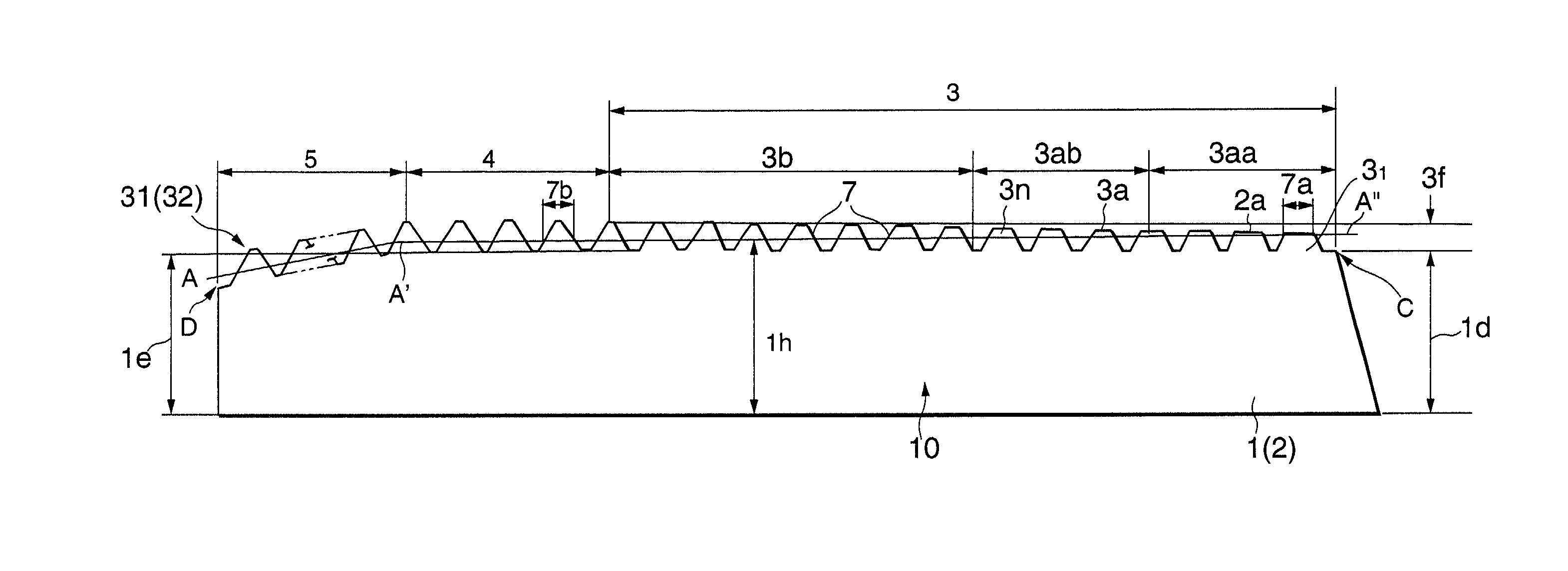
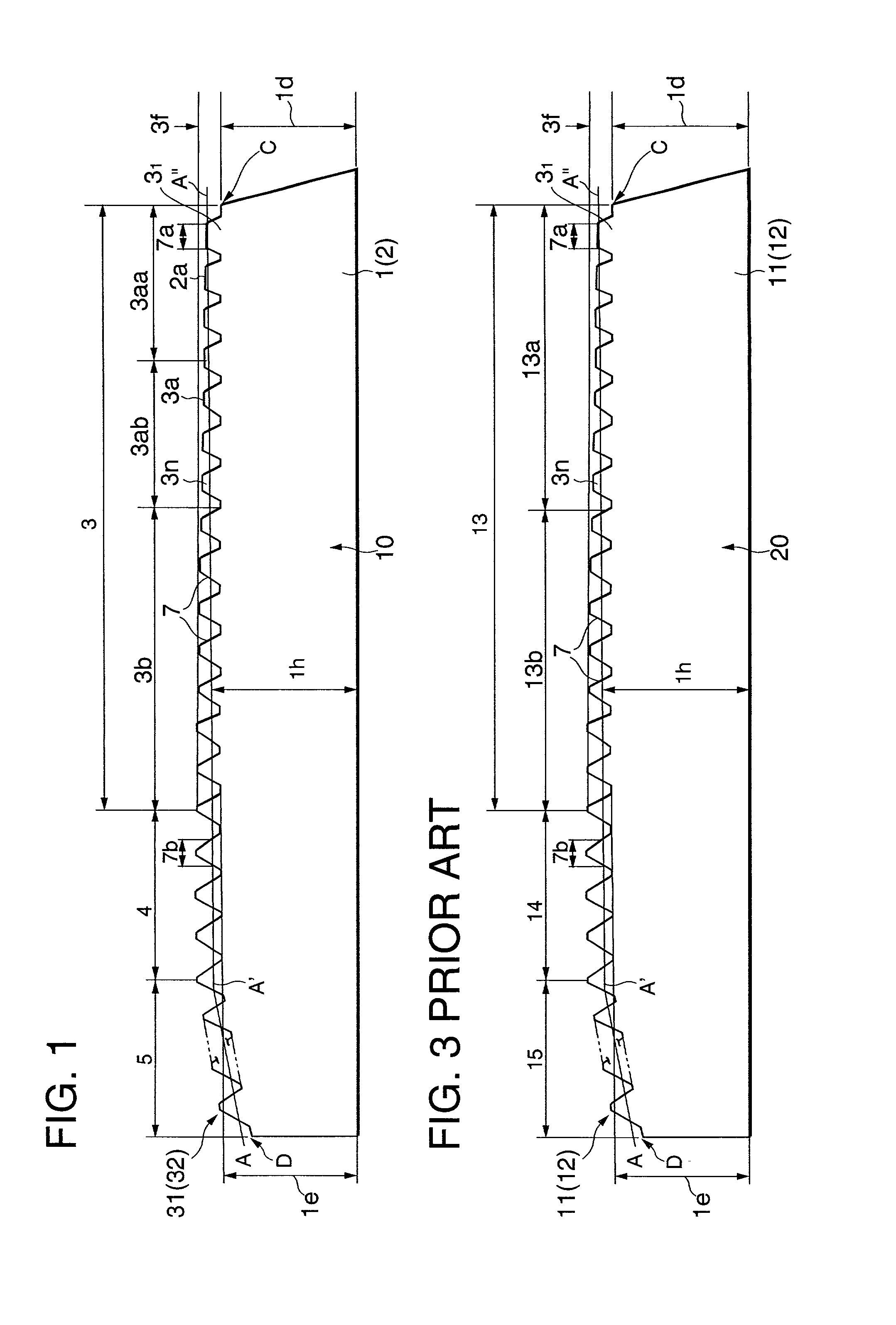
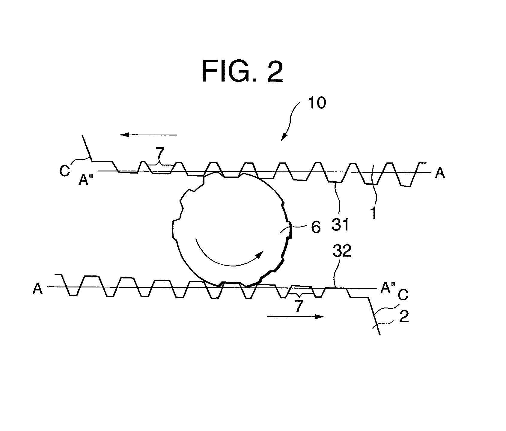
[0023] Involute splines are formed on the periphery of cylindrical workpieces using a pair of tooth rolling flat dies shown in FIGS. 1 and 2 by semi-dry forming in which a very small amount of oil mist is sprayed on the workpieces to be rolled. The dimensions of the involute splines are; module: 1.058pressure angle: 30.degree. and face width of the spline: 20 mm. The results showed that the same or more longer service life as that of using a pair of conventional tooth rolling flat dies shown in FIG. 3 conducted by the wet forming is achieved even if the forming is conducted using the tooth rolling flat dies shown in FIGS. 1 and 2 by the semi-dry forming. This means that according to the tooth rolling flat dies, since the surface roughness Rz of the teeth of the second substantially quarter length portion of the leading teeth section is made fine, the stress concentration thereon is decreased, thereby the damage on the teeth of the substantially quarter length portion area is deterre...


PUM

PropertyMeasurementUnit
surface roughness Rzaaaaaaaaaa
surface roughness Hzaaaaaaaaaa
surface roughness Rzaaaaaaaaaa

Abstract

A tooth rolling flat die and a method for forming a tooth are provided. The die has the same service life as those of the conventional tooth rolling flat dies using oil coolant even if conducted by semi-dry forming. Wherein the die comprises the surface roughness Rz of the first substantially quarter length portion of the leading teeth section wherein heights of the tops of the teeth are gradually increasing, ranging 20 to 35 mum, and that Rz of the second substantially quarter length portion of the leading teeth section, ranging 5 to 20 mum. The die is adapted for semi-dry forming the tooth.

Description

[0001] 1. Field of the Invention[0002] The present invention relates generally to tooth rolling flat dies for forming teeth, such as spline teeth and gear teeth on the periphery of cylindrical workpieces, and in particular to tooth rolling flat dies and a method for forming the teeth which are adapted for forming the teeth by semi-dry forming in which a very small amount of oil mist is sprayed on the workpieces to be rolled.[0003] 2. Description of the Related Art[0004] Tooth rolling flat dies are known means for forming teeth, such as spline teeth and gear teeth on the periphery of cylindrical workpieces, and are generally rectangular plate members having one working surface thereon toothed. These teeth include alternate ridges and grooves, which conform in plan to the shape of the teeth to be rolled. The teeth run the length of the die face. The dies are used in mating pair with their toothed working faces facing each other. A cylindrical workpiece of the teeth to be rolled is pla...

Claims


Application Information

Patent Timeline
18 Apr 2002
Publication
US20020043094A1
IPC
B21H3/06; B21H5/02
CPC
B21H5/027; B21H3/06
Inventors
MURAI, YASUHIRO; KUMAGAI, TAKAHIRO