Traveling-wave amplifier having a II -type output transmission line structure

a technology of transmission line and travel wave amplifier, which is applied in the direction of amplifiers, amplifiers with coupling networks, amplifiers with semiconductor devices/discharge tubes, etc., can solve the problems of inability to achieve the expected gain-bandwidth product improvement, inability to meet the above two matching conditions simultaneously, and inability to achieve impedance and velocity matching conditions

Inactive Publication Date: 2002-04-25
GWANGJU INST OF SCI & TECH
View PDF6 Cites 1 Cited by
  • Summary
  • Abstract
  • Description
  • Claims
  • Application Information

AI Technical Summary

Problems solved by technology

Thus, the expected gain-bandwidth product improvement cannot be achieved.
However, the above two matching conditions cannot be satisfied simultaneously for the structure of the traveling-wave amplifier shown in FIG. 1.
This indicates that impedance and velocity matching conditions cannot be achieved and improvement in gain-bandwidth product of the simple traveling-wave amplifier structure shown in FIG. 1 is limited.
When the additional element values attached in T-type or m-derived-type drain line structures are increased to improve the bandwidth of the amplifiers, the gain peaking at the high frequency increases rapidly, degrading the stability of the amplifiers.
In conclusion improvement of gain-bandwidth product of the two conventional traveling-wave amplifiers (having T-type drain line structure in FIG. 3 and m-derived drain line structure in FIG. 4) is limited due to the amplifier's stability problem associated with the additional elements directly connected to the output of unit transistors and the feedback capacitance C.sub.gd.

Method used


Image

  • Traveling-wave amplifier having a II -type output transmission line structure
  • Traveling-wave amplifier having a II -type output transmission line structure
  • Traveling-wave amplifier having a II -type output transmission line structure

Examples


Embodiment Construction

[0047] The composition and operation of the present invention according to the preferred embodiment of the present invention will be explained with reference to the accompanying drawings.

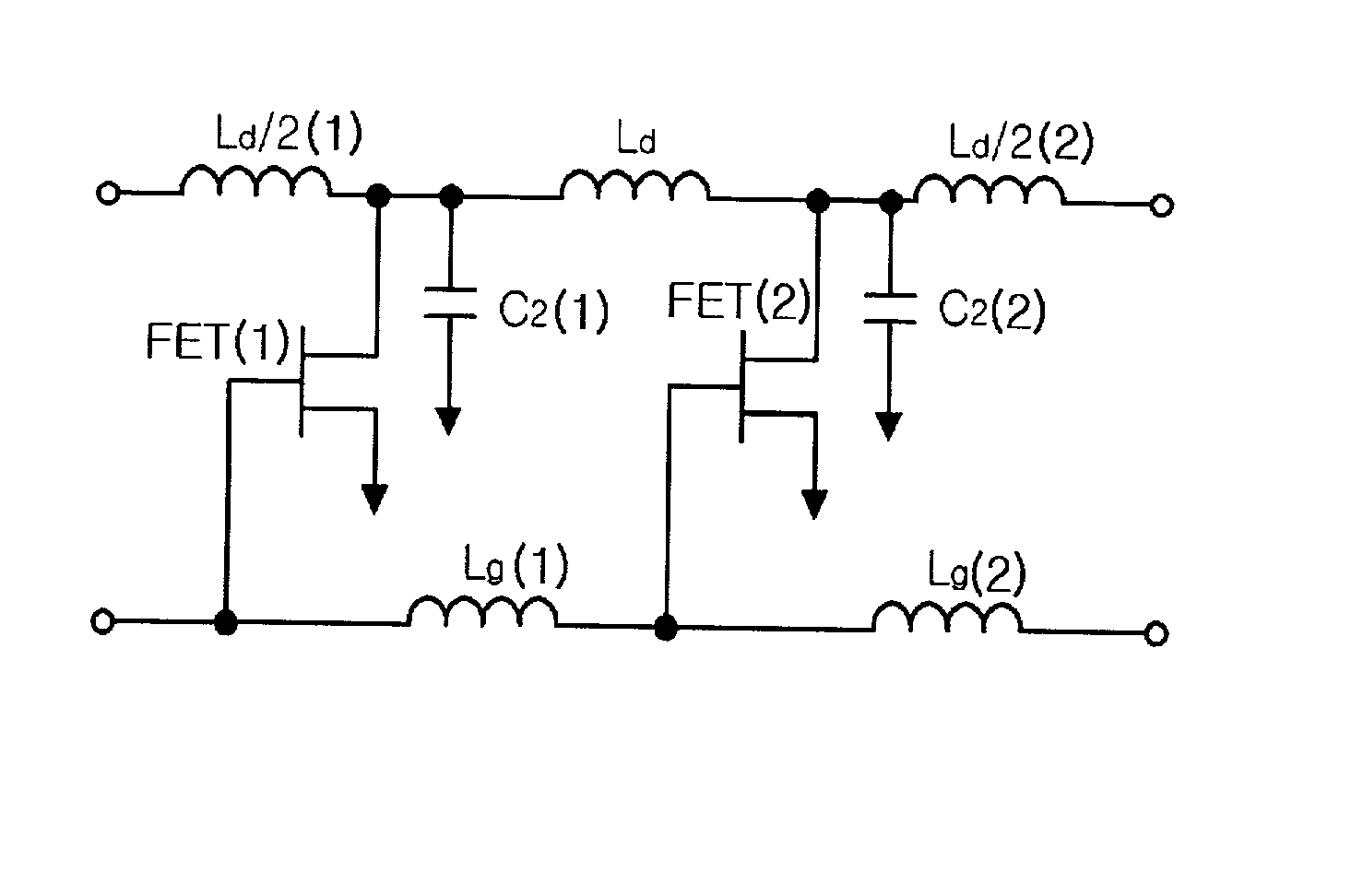
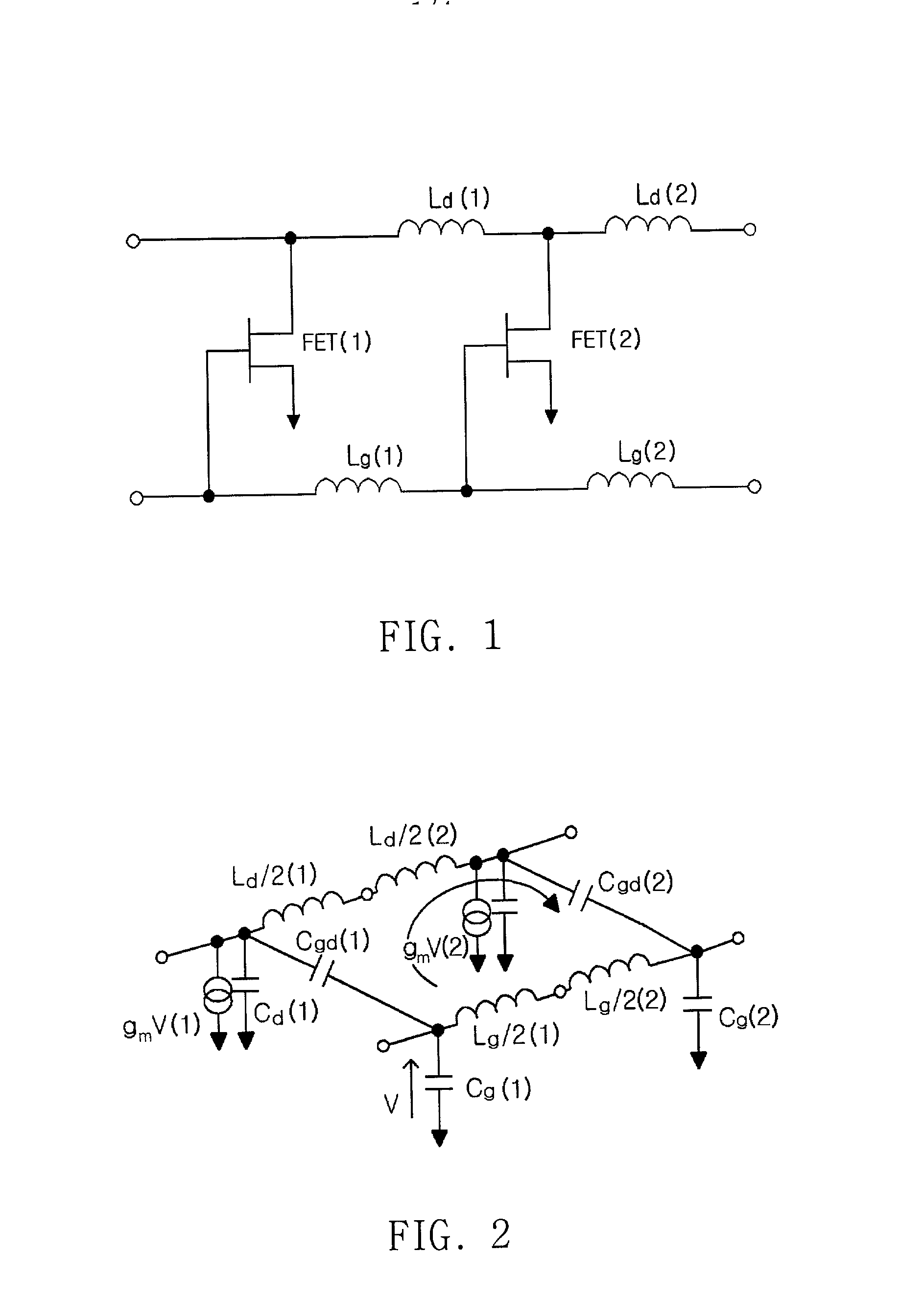
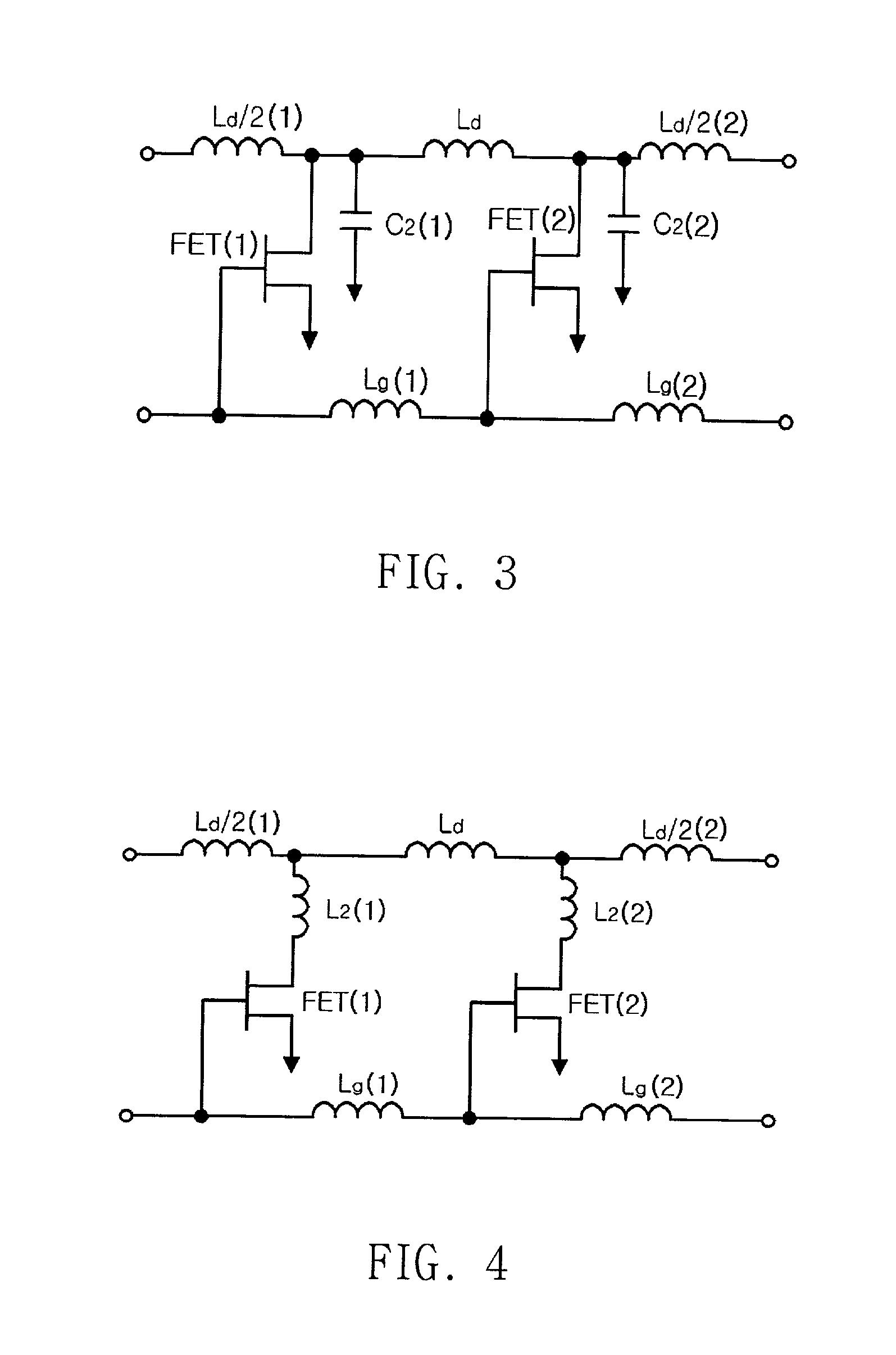
[0048] FIG. 8 is a circuit diagram (a sub-section of a multi-stage amplifier) of a traveling-wave amplifier having .pi.-type drain transmission line according to the present invention and FIG. 9 is a circuit diagram (a sub-section of a multi-stage amplifier) which shows the location of additional capacitance in the traveling-wave amplifier having .pi.-type drain transmission line according to the present invention.

[0049] In FIG. 8, the drain terminal of FET(1) is connected between drain line L.sub.d / 2(1) and L.sub.d / 2(2), and the additional capacitance C.sub.3(1) is connected between drain line L.sub.d / 2(2) and L.sub.d / 2(3).

[0050] Also, the drain terminal of FET(2) is connected between drain line L.sub.d / 2(3) and L.sub.d / 2(4), and the additional capacitance C.sub.3(2) is connected to the drain line ...


PUM


Abstract

The present invention relates to the traveling-wave amplifier having a pi-type output transmission line structure. In traveling-wave amplifiers having conventional output line structures including T-line and m-derived-line structures, additional capacitance and inductance are attached to the output of the transistors for velocity matching in input/output transmission lines in order to improve gain-bandwidth product. However, it is difficult to achieve velocity matching of output/input transmission lines without stability problem due to the influence of the additional capacitance and inductance through the feedback capacitance of the transistor used. The present invention provides the traveling-wave amplifier having a pi-type output transmission line structure, where the additional capacitance used for velocity matching of input/output transmission lines is connected in the middle of the output line. Since the additional element is isolated from the output of the transistor by the output transmission line, the pi-type output transmission line structure can achieve velocity matching of output/input transmission lines without stability problem associated with the additional capacitance and the feedback capacitance of the transistor. The traveling-wave amplifier having a pi-type output transmission line structure has an improved bandwidth, gain flatness, and stability compared to traveling-wave amplifiers having the conventional output line structures.

Description

[0001] 1. Field of the Invention[0002] The present invention relates to a traveling-wave amplifier having a .pi.-type output transmission line structure.[0003] More particularly, it relates to the technique wherein improved bandwidth characteristics without degradation of stability of the traveling-wave amplifier can be gained by separating additional capacitances used for matching of the velocity of traveling-waves in the input and output transmission lines from the output of unit transistors.[0004] 2. Description of the Related Art[0005] A traveling-wave amplifier is an ultra-wide-band amplifier and is widely used for microwave and millimeter-wave applications. It can be used as ultra-wide-band amplifiers in wireless communications and optical receivers in optical communications and microwave / millimeter wave-optical communications.[0006] The bandwidth of ordinary amplifiers is typically limited to less than approximately 30% of the cutoff frequency(f.sub.T) of the unit transistor ...

Claims


Application Information

Patent Timeline
Patent Type & Authority Applications(United States)
IPC IPC(8): H03F3/60
CPCH03F3/607H03F3/60
Inventor SONG, JONG INLEE, JUNG SUN
Owner GWANGJU INST OF SCI & TECH
Why Eureka
Try Eureka