Method and apparatus for measuring optical aberrations of the human eye

a technology of optical aberration and human eye, which is applied in the field of human eye optical aberration measurement methods and apparatuses, can solve the problems of less than optimal images generated, complex systems, and high cost of visual system maximization, and achieve accurate and rapid measurement of eye optical aberrations

Inactive Publication Date: 2002-04-25
AOPTIX TECH
View PDF0 Cites 79 Cited by
  • Summary
  • Abstract
  • Description
  • Claims
  • Application Information

AI Technical Summary

Benefits of technology

0022] It is a primary object of the present invention to provide both a method and an apparatus for accurately and quickly measuring the optical aberrations of the eye, including focus, astigmatism and higher order aberrations.

Problems solved by technology

These systems are typically complex and expensive and most require access to the focal plane.
Nevertheless, the measurement and characterization of these aberrations, primarily the monochromatic aberrations, has remained a problem and has fostered much research in physiological optics over the years.
None of the present methods allow for correction of other aberrations and thus do not maximize the optical potential of the visual system, leaving the images generated to be less than optimal.
In addition, not only is the view out of the eye not optimal but so is the view in.
Thus, the examination of the eye's interior is also limited by these aberrations, and in some clinical situations, is severely handicapped.
Also, many subject's have irregularly shaped corneas, not currently treatable.
Clinical studies have indicated that current autorefractors, when used to determine the refraction, or optical prescription, of surgically modified eyes may provide less reliable data in such cases.
Even in normal eyes, their accuracy is such that the information cannot be routinely relied upon but must be verified by further subjective testing.
It is apparent that a complete diagnosis and understanding of the eye's optical function, as the organic optical instrument, is currently very limited.
However, because of the optical aberrations of the eye, a degraded or blurred image is created on the retina.
Unfortunately, current subjective clinical methodology and instrumentation, such as the phoropter and objective devices such as autorefractors, do not avail themselves of this understanding and are based on concepts and techniques that restrict measurements to defocus and astigmatism only.
However, they gather optical information about only one surface in the eye's refractive system and reveal nothing about the system as a whole.
Initially this work, such as present by M. S. Smirnov ("Measurement of the Wave Aberration of the Human Eye", Biophysics, 1961; 6:776-94) was carried out using subjective sequential subject testing, which was inaccurate and time consuming.
This results in an aberrated image of the grid on the retina that can be photographed and analyzed by ray tracing.
Other drawbacks were the lack of a rapid means of analysis and the faulty assumption that the aberrations could be characterized by terms of only up to the fourth order.
An acknowledged limitation of the system was that only polynomials up to the fourth degree were used to represent the wavefront, which is considered inadequate (Williams U.S. Pat. No. 5,777,719).
Disadvantages with this technique are the complexity, construction and cost of the Hartman-Shack wavefront sensor.
In addition, the deformable mirror described is extremely complex and costly to construct.
Although perhaps capable of determining and neutralizing the wavefront, the design does not describe how the device could be used as a common tool in clinical practice to determine the refraction of the eye in an economical way.

Method used


Image

  • Method and apparatus for measuring optical aberrations of the human eye
  • Method and apparatus for measuring optical aberrations of the human eye
  • Method and apparatus for measuring optical aberrations of the human eye

Examples


Embodiment Construction

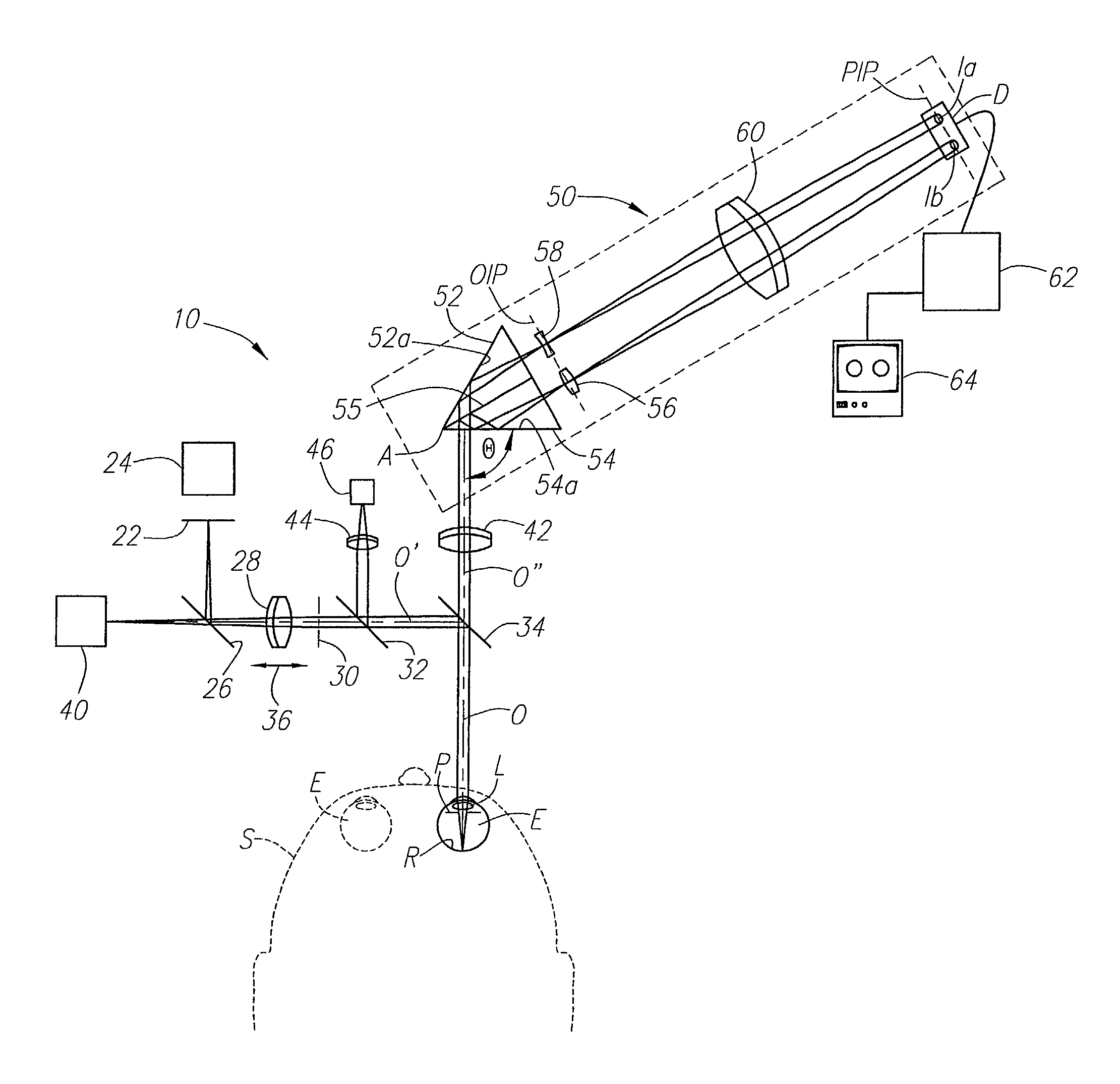
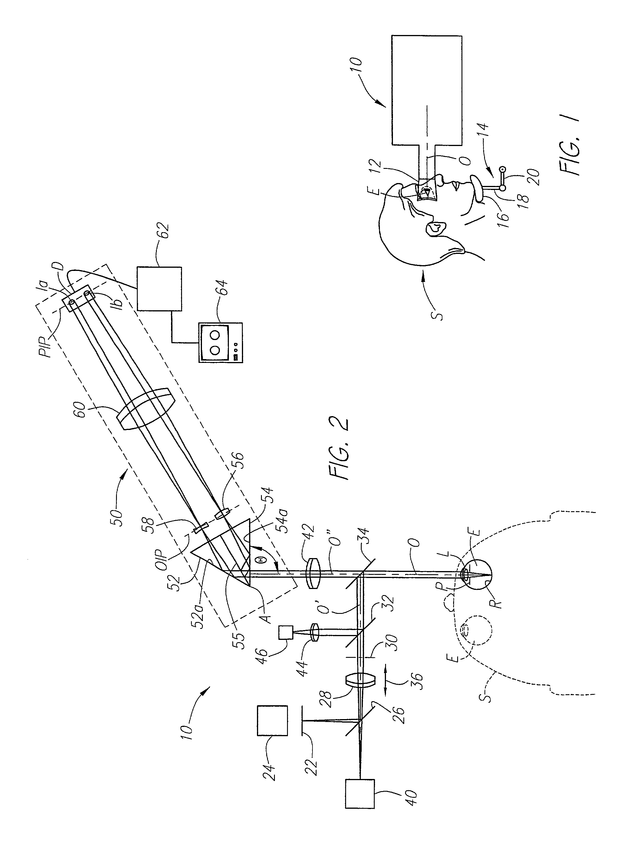
[0035] Referring now to FIGS. 1 and 2, the subject person S that is to have his or her eyes analyzed by the optical apparatus, generally designated 10, of the present invention positions one eye against a flexible eye cup 12 for aligning the center of the pupil of that eye with the optical axis O of the apparatus 10. Preferably, the head of the subject person S is adjusted to obtain that alignment and then supported in that position by any convenient means, such as an adjustable chin support 14. For example, a shaped pad 16 may be supported by a pair of pivotally connected links 18 and 20 that can be manipulated and then locked in position when the subject person S has his or her eye E in appropriate alignment with the optical axis O, which alignment can be determined by the operator of the apparatus in a manner described below. For clarity of illustration, the eye cup 12 is omitted from the schematic plan view FIG. 2.

[0036] Referring more particularly to FIG. 2, the optical apparat...


PUM


Abstract

An apparatus for measuring optical aberrations of the human eye wherein the person positions his or her eye on an optical axis of the apparatus and looks at an illuminated target on the optical axis that is visible to the eye for allowing the eye to focus on the target and establish a position of the eye. A collimating lens on the optical axis is movable along the optical axis for adjusting the apparent optical distance between the eye and the target. A light source directs a predetermined light beam along the optical axis into the eye and onto the retina of the eye as a spot of light. A lens reimages the light scattered from the light spot on the eye retina into a wavefront curvature sensor that forms two oppositely defocused images on an image detector, and a computer processes and analyzes the two defocused images for measuring the optical aberrations of the eye.

Description

[0001] This application basis priority on Provisional Patent Application Serial No. 601178,416, filed Jan. 27, 2000.[0002] The present invention relates to methods and optical instrumentation for objectively measuring the aberrations of the human eye and specifically to an instrument capable of measuring not only the focus (spherical) and astigmatism (cylindrical) characteristics and aberrations of a person's eye but also all of the lower and higher order optical aberrations that are derived from a measured wavefront utilizing a wavefront curvature sensor.[0003] Measuring the aberrations of an optical system, including a human eye, is an important part of working with any optical system. Existing methods of measurement include various interferometric techniques, the Shack-Hartman wavefront sensor, and various systems involving the projection of patterns through the optical system. These systems are typically complex and expensive and most require access to the focal plane.[0004] The...

Claims


Application Information

Patent Timeline
Patent Type & Authority Applications(United States)
IPC IPC(8): A61B3/103G02B26/06
CPCA61B3/103G02B26/06
Inventor GRAVES, J. ELONNORTHCOTT, MALCOLM J.
Owner AOPTIX TECH
Why Eureka
Try Eureka