Automatic fiber preparation unit for splicing

a fiber preparation unit and automatic technology, applied in the direction of cleaning flexible articles, cleaning using liquids, instruments, etc., can solve the problems of high labor intensity, low quality of splicing, and large machine size and weigh

Inactive Publication Date: 2002-05-30
AMHERST HLDG
View PDF0 Cites 29 Cited by
  • Summary
  • Abstract
  • Description
  • Claims
  • Application Information

AI Technical Summary

Problems solved by technology

If an optical fiber is not prepared properly, the quality of the splice will be low regardless of the care taken in the splicing step.
However, these machines are often quite large and heavy.
Also, the fiber preparation stage is manually intensive normally requiring human interaction to move the fibers from machine to machine to prepare the fibers for splicing.
This human interaction can be time consuming and result in high labor costs.
Additionally, operator handling of the optical fibers between stages increases the risk of scratching and contaminating the fibers before splicing.
This may lead to unsatisfactory splices that reduce the performance of the splices or require the splices to be discarded.
Such techniques are more likely to damage optical fibers as they are rather delicate, especially once optical fibers have been stripped.

Method used


Image

  • Automatic fiber preparation unit for splicing
  • Automatic fiber preparation unit for splicing
  • Automatic fiber preparation unit for splicing

Examples


Embodiment Construction

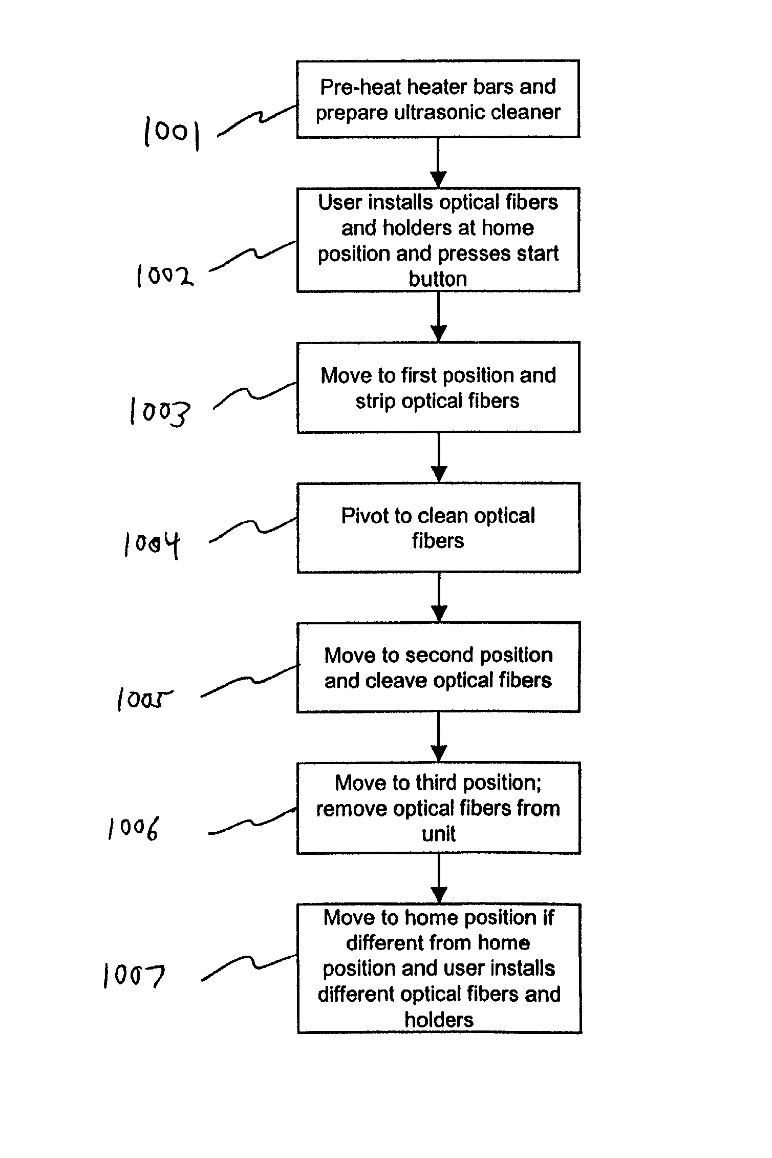
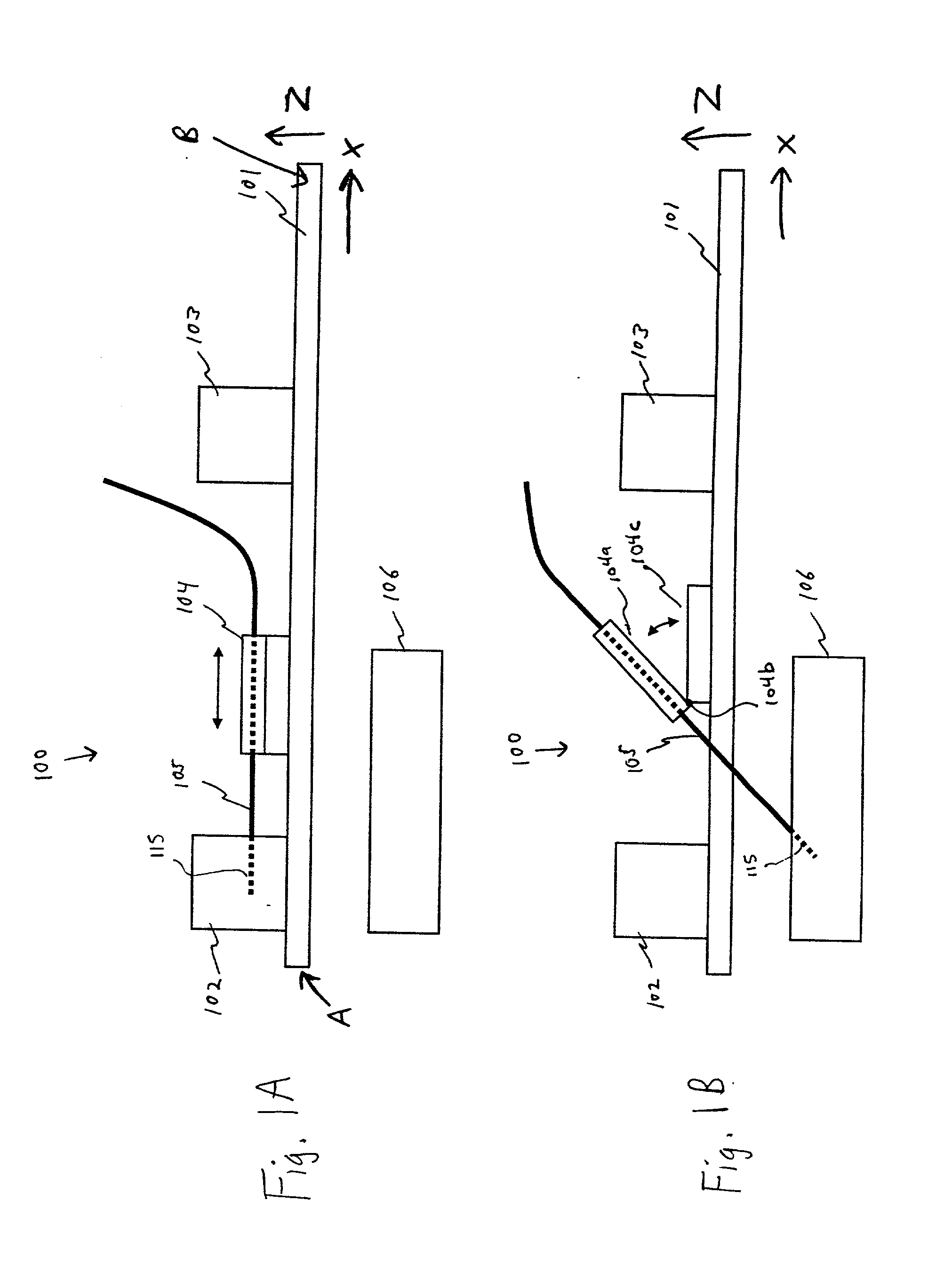
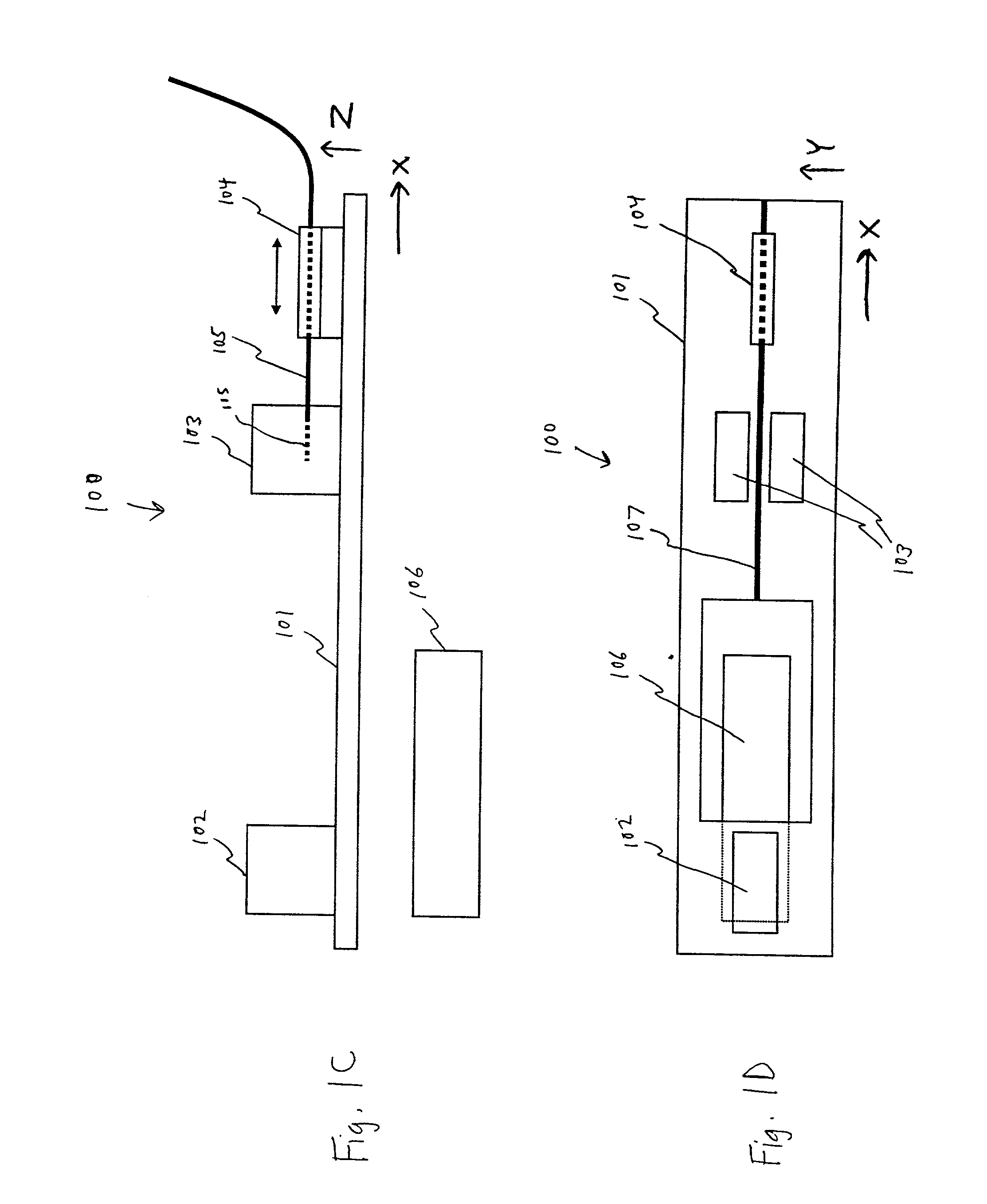
[0040] Referring to FIGS. 1A-1C, an exemplary automatic fiber preparation unit 100 (hereafter referred to as "unit 100") is shown. This unit 100 is used to prepare optical fibers for splicing or attachment to a connector or an optical component. The unit 100 may include a main body 101 and a carriage 104 moveably coupled with to the main body 101. The term "main body" is a general term that includes within its scope a frame, casing, chassis, housing, body, or other similar structure. In the present example, the carriage 104 may slide along the main body 101 in a single dimension or axis (e.g., along the X-axis in the embodiment shown) in the manner shown by the arrows in FIG. 1A. An optical fiber 105 is coupled to the carriage 104 via a fiber holder or any other desired manner. In a preferred embodiment, the carriage 104 translates along an axis parallel to the longitudinal axis of the optical fiber 105 relative to the main body 101. The term "translate" as used herein refers to a m...


PUM


Abstract

Apparatuses and methods for automatically preparing optical fibers for splicing (or for attachment to a connector or an optical component) by automatically positioning a stripping station, a cleaning station, and a cleaving station to process one or more optical fibers substantially simultaneously. The optical fiber may be held at a fixed position during processing. A vacuum system may further be used to automatically collect scrap produced by the cleaving process.

Description

[0001] The present application claims priority to U.S. patent application Ser. No. 09 / 725,054, entitled "Automatic Fiber Preparation Unit for Splicing," filed Nov. 29, 2000, which is incorporated by reference herein as to its entirety.[0002] The present invention relates to apparatuses and methods for automatically preparing optical fibers for uses such as splicing or attachment to a connector or optical component, and more particularly to an automatic fiber preparation unit that prepares an optical fiber by automatically positioning an optical fiber at a stripping station, a cleaning station, and a cleaving station, and methods relating thereto.[0003] In the optical fiber industry, preparing optical fibers for splicing or attachment to a connector or an optical component is a common practice. For example, to splice two optical fibers together, the following steps are usually performed in the following order: stripping of the protective coating from a portion of the ends of the opti...

Claims


Application Information

Patent Timeline
Patent Type & Authority Applications(United States)
IPC IPC(8): B08B3/12G02B6/24B08B11/00G02B6/00G02B6/245G02B6/25G02B6/255G02B6/44
CPCG02B6/245G02B6/2551G02B6/25
Inventor WARE, SCOT K.CLARK, BRETT G.CRIPPS, MICHAEL ROYCE JR.SELLERS, DAVID WAYNEMEITZLER, JARED CASSIDYTROYER, JASON THOMAS
Owner AMHERST HLDG
Why Eureka
Try Eureka