Fiber for compensating chromatic dispersion of a monomode fiber in band S

a monomode fiber and fiber technology, applied in the direction of optical fibers with desired dispersion, cladded optical fibres, instruments, etc., can solve the problems of chromatic dispersion slope, particularly severe chromatic dispersion, and more severe problems

Inactive Publication Date: 2002-06-06
ALCATEL LUCENT SAS
View PDF0 Cites 17 Cited by
  • Summary
  • Abstract
  • Description
  • Claims
  • Application Information

AI Technical Summary

Benefits of technology

0013] It is also advantageous for the fiber to present a theoretical cutoff wavelength longer than

Problems solved by technology

This problem of compensating chromatic dispersion and chromatic dispersion slope is particularly severe with very high bit rate transmission systems, typically for WDM transmission sys

Method used


Image

  • Fiber for compensating chromatic dispersion of a monomode fiber in band S
  • Fiber for compensating chromatic dispersion of a monomode fiber in band S
  • Fiber for compensating chromatic dispersion of a monomode fiber in band S

Examples


Embodiment Construction

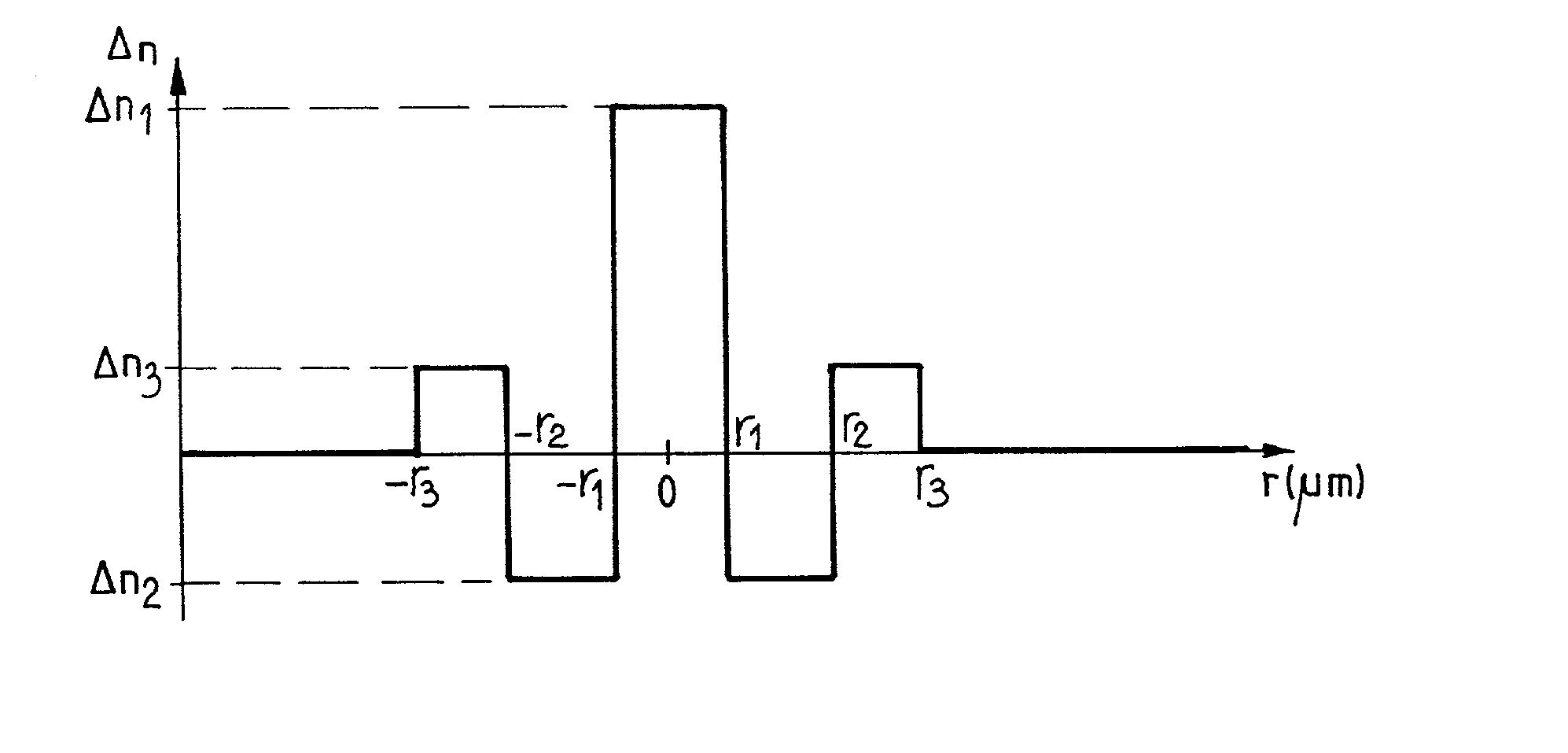
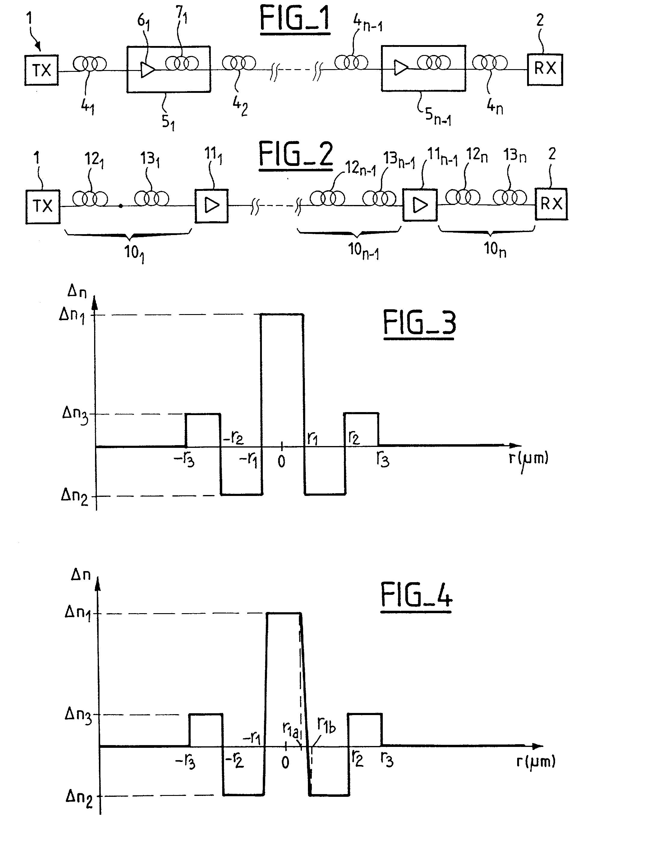
[0027] The invention proposes a chromatic dispersion-compensating fiber suitable for compensating the chromatic dispersion of a step index monomode fiber in band S. The fiber is monomode at 1475 nm. It has chromatic dispersion of less than -40 ps / (nm.multidot.km) around 1475 nm, a chromatic dispersion slope less than -0.16 ps / (nm.sup.2.multidot.km), and an effective section area greater than or equal to 14 .mu.m.sup.2 around said wavelength value. It is also possible to provide for the ratio of the chromatic dispersion over the chromatic dispersion slope to present the value of less than 250 nm around said wavelength of 1475 nm, this ensures that the cumulative dispersion in each channel in the range 1450 nm to 1500 nm has an absolute value of less than 70 ps / nm, on average for transmission over 100 km when the fiber is used as a compensation fiber for an SMF.

[0028] The fiber of the invention makes it possible to compensate chromatic dispersion and chromatic dispersion slope for tra...


PUM


Abstract

A chromatic dispersion-compensating fiber adapted to compensate the chromatic dispersion of a step index monomode fiber in band S presents chromatic dispersion of less than -40 ps/(nm.km) around 1475 nm, chromatic dispersion slope of less than -0.16 ps/(nm2.km), and an effective area greater than or equal to 14 mum2 around said wavelength value. The fiber is monomode at 1475 nm. The fiber can present a rectangle profile with a buried trench and a ring. It serves to compensate chromatic dispersion and chromatic dispersion slope for transmission systems in band S using a step index monomode fiber as the line fiber.

Description

[0001] The present invention relates to the field of optical fiber transmission, and more specifically it relates to compensating chromatic dispersion and chromatic dispersion slope in optical fiber transmission systems.[0002] The refractive index profile of an optical fiber is generally described in terms of the appearance of a graph plotting the refracting index to the fiber as a function of radius. The distance r from the center of the fiber is conventionally plotted along the abscissa, and the difference in refractive index relative to that of the cladding of the fiber is plotted up the ordinate. The term "step", "trapezium", and "triangle" are therefore used with respect to index profiles whose graphs are respectively step-shaped, trapezium-shaped, and triangular. These curves are generally representative of the ideal or theoretical profile for the fiber, and fiber manufacturing constraints can yield a profile that departs perceptibly therefrom.[0003] In new high bit rate trans...

Claims


Application Information

Patent Timeline
IPC IPC(8): G02B6/34G02B6/036
CPCG02B6/02009G02B6/02261G02B6/29377G02B6/0281G02B6/03644G02B6/0228
Inventor FLEURY, LUDOVICBEAUMONT, FLORENTSILLARD, PIERREDE MONTMORILLON, LOUIS-ANNEGORLIER, MAXIMENOUCHI, PASCALE
Owner ALCATEL LUCENT SAS
Why Eureka
Try Eureka