[0009] In this first relay welding detector of the present invention, when it is determined that the secondary battery is not being recharged or discharged while the power line is connected by the relay, the interruption instructing device instructs interruption of the power line by the relay, and when the interruption is instructed, the welding judging device judges welding of the relay. According to the first relay welding detector of the present invention, when it is determined that the secondary battery is not being recharged or discharged, the relay is interrupted and its welding is judged, even if the power line is connected by the relay, such that welding judgement can be performed more frequently. As a result, welding of the relay can be detected earlier.
[0011] The first relay welding detector of the present invention may comprise a
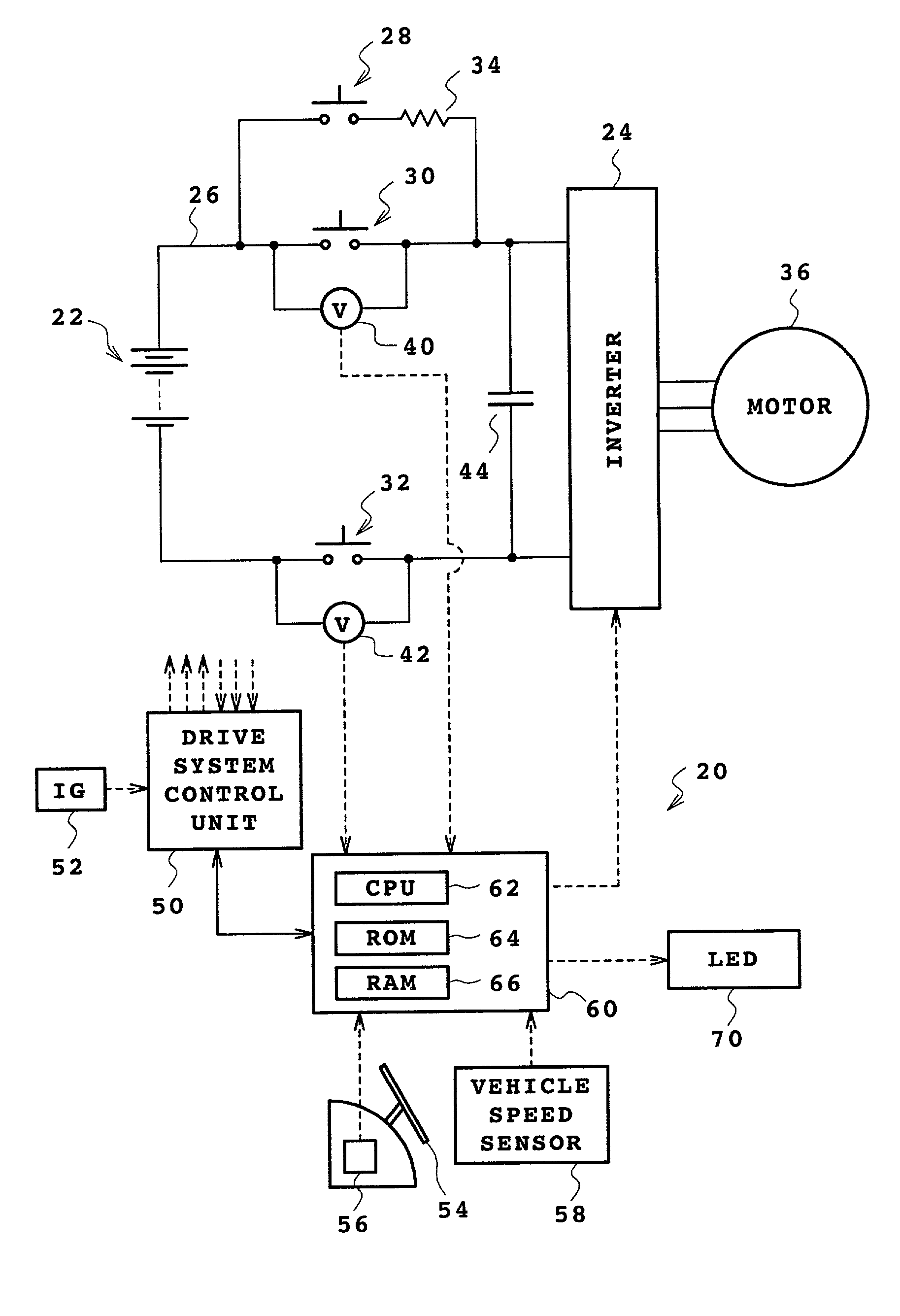
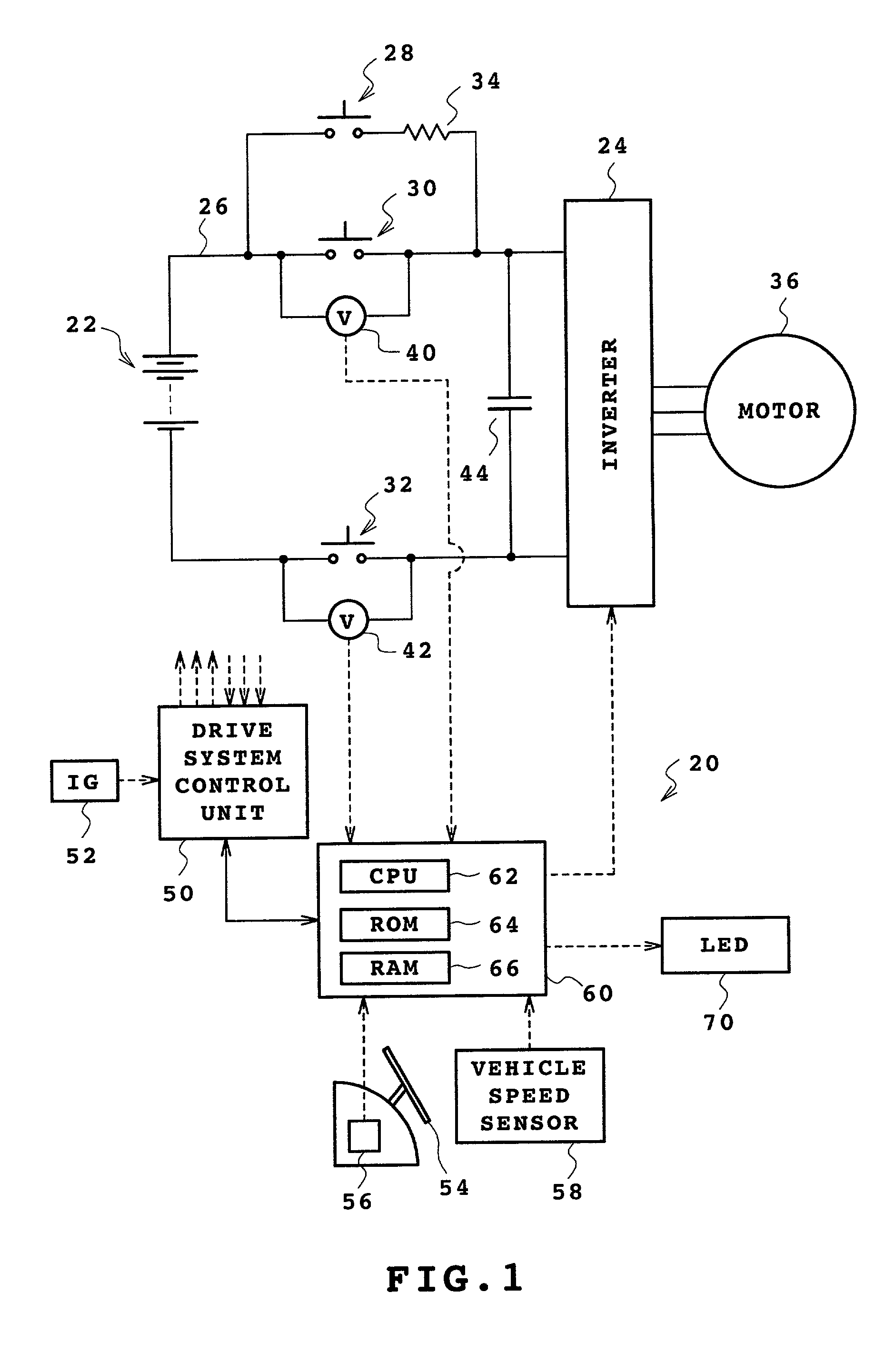
capacitor disposed between the relay and the switching element and a
voltage lowering device which lowers the
voltage of the
capacitor when the interruption instructing device instructs to interrupt the power line by the relay, wherein the welding judging device is a device for judging welding of the relay when the
voltage of the capacitor is lowered by the voltage lowering device. Thus, the
electric charge stored in the capacitor can be discharged faster, and welding of the relay can be judged more accurately.
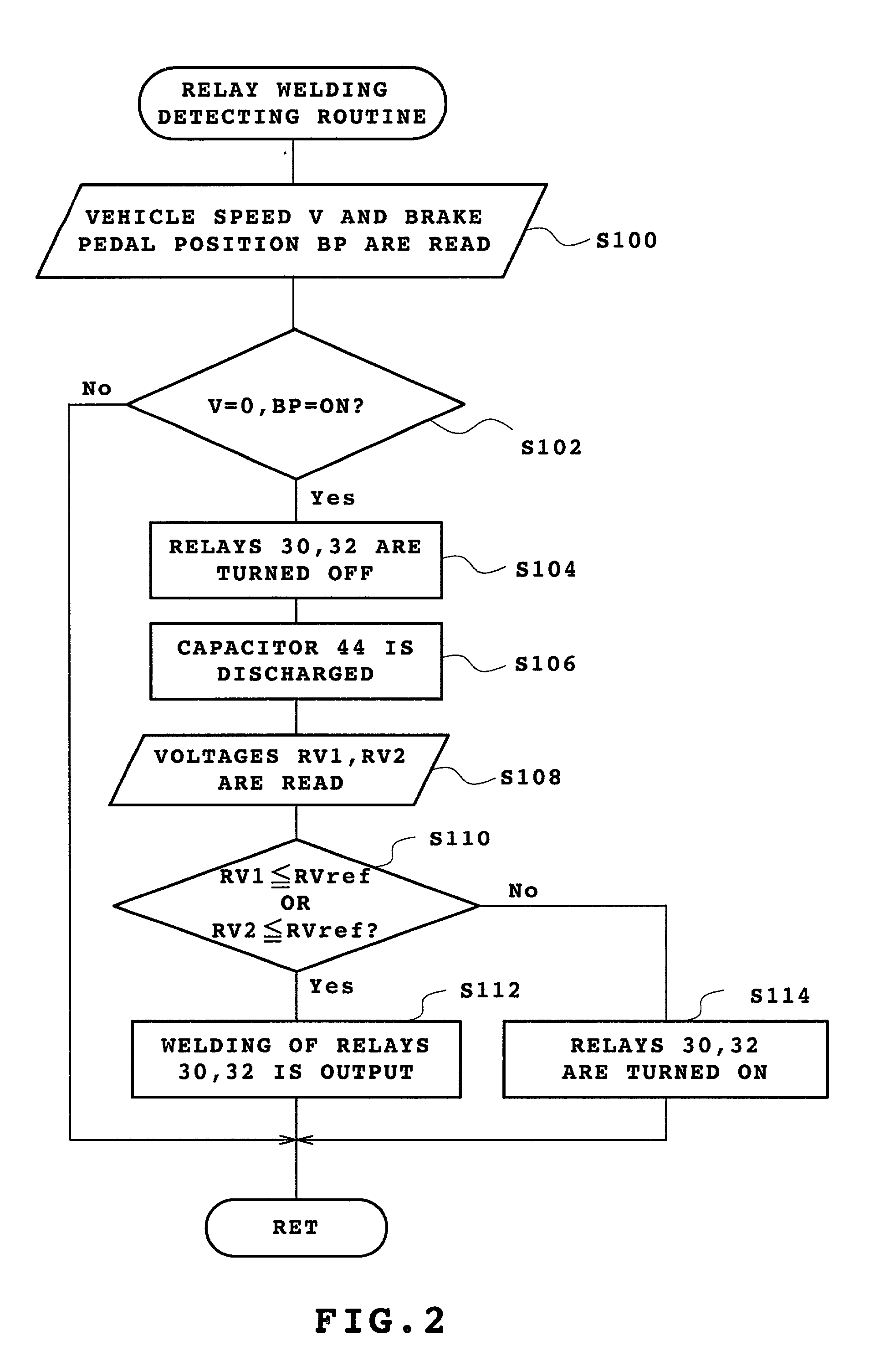
[0014] In the second relay welding detector of the present invention, when the running speed of the vehicle detected by the running speed detector is approximately 0 with the power line connected by the relay and the operation of brakes is detected by the braking operation detector, the interruption instructing device instructs interruption of the relay, and, when the interruption is instructed, the welding judging device judges the welding of the relay. According to the second relay welding detector of the present invention, when the vehicle has substantially stopped and the brakes are applied, welding of the relay can be judged by instructing disconnection of the power line by the relay even if the power line is connected by the relay. As a result, a frequency of judging the welding of the relay can be increased, and the welding of the relay can be detected earlier.
[0017] In the method for detecting welding of a relay of the present invention, when it is determined that the secondary battery is not being recharged or discharged while the power line is connected by the relay, the interruption of the power line by the relay is instructed, and, when the interruption is instructed, the welding of the relay is judged. According to the method for detecting welding of a relay of the present invention, when it is determined that the secondary battery is not being recharged or discharged, the relay is interrupted and its welding is judged, even if the power line is connected by the relay, such that welding judgment can be performed more frequently. As a result, welding of the relay can be detected earlier.
[0019] The method for detecting welding of a relay of the present invention may further comprise a step (d) for lowering the voltage of a capacitor which is disposed between the relay and the switching element when the step (b) instructs interruption of the power line by the relay, wherein the step (c) may be a step for judging welding of the relay when the voltage of the capacitor is lowered by the step (d). Thus, the
electric charge stored in the capacitor can be discharged faster, and welding of the relay can be judged more accurately.

