Method of assembling a fuel injector for the combustion chamber of a turbomachine

a technology of turbomachine and fuel injector, which is applied in the direction of machines/engines, soldering devices, light and heating equipment, etc., can solve the problems of complex manufacturing and assembly, considerable reduction, performance degradation, etc., and achieve the effect of reducing the above-mentioned drawbacks

Inactive Publication Date: 2002-06-20
HISPANO SUIZA SA
View PDF0 Cites 25 Cited by
  • Summary
  • Abstract
  • Description
  • Claims
  • Application Information

AI Technical Summary

Benefits of technology

0005] The present invention provides a method of assembling the end portion of an injector which mitigates the above-mentioned drawbacks. An object of the invention is thus to make the end portion with a minimum number of parts and in a small space. Another object of the invention is to integrate a cooling circuit in this end portion of an injector so as to enable the injector to be used at very high temperature.

Problems solved by technology

This results firstly in such injectors being complex to manufacture and assemble, and secondly, under certain operating conditions and in particular at high temperatures, in performance being degraded because of a considerable reduction in the lifetime of the combustion chamber and / or of the turbine, or indeed because of destruction of the injector and corresponding destruction of the turbomachine.

Method used


Image

  • Method of assembling a fuel injector for the combustion chamber of a turbomachine
  • Method of assembling a fuel injector for the combustion chamber of a turbomachine
  • Method of assembling a fuel injector for the combustion chamber of a turbomachine

Examples


Embodiment Construction

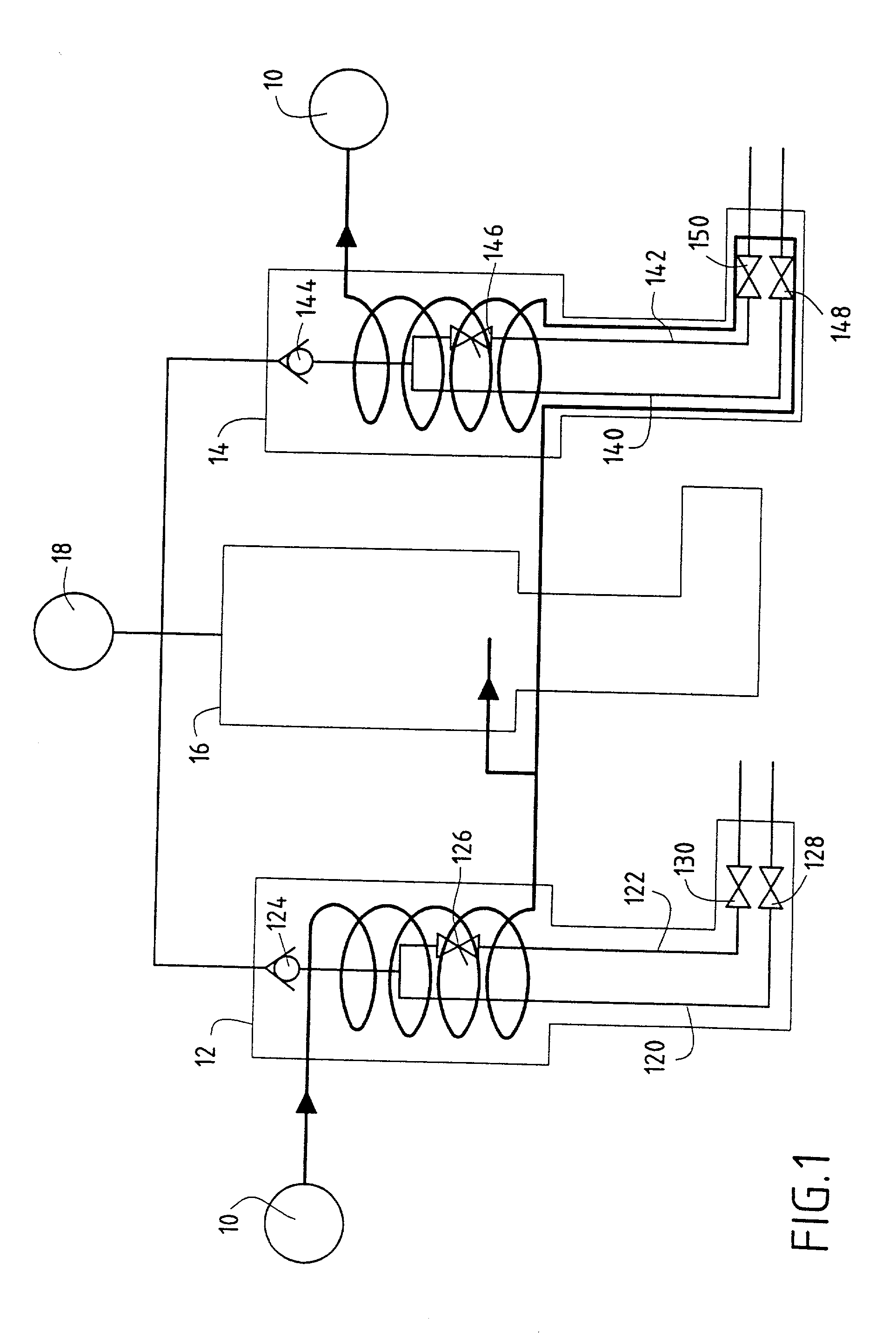
[0020] FIG. 1 is a schematic showing the fuel and cooling circuits for injectors in a two-headed annular combustion chamber of a turbomachine.

[0021] The cooling circuit is shown only for two injectors so as to make it easier to understand (such a combustion chamber can have as many as 20 pilot injectors and 40 main injectors, for example, where such numbers are not limiting), and it is fed from a feed source 10 by a cooling fluid which is optionally independent (such as oil, water, or any other suitable fluid) which passes firstly through a "pilot" injector 12 for starting the turbomachine and for running it while idling (at low power), and then fed in parallel to two "main" injectors 14, 16 (organized on the basis of one even rank and one odd rank), which injectors enable the machine to operate during cruising stages (and in particular at full power). The cooling fluid then returns to the feed source 10, thereby closing the cooling circuit (naturally this circuit also includes in c...


PUM

PropertyMeasurementUnit
temperatureaaaaaaaaaa
diameteraaaaaaaaaa

Abstract

An assembly method in which a brazing metal is initially filled into radial wells pierced in an annular injection piece having first injection orifices for discharging a primary fuel, and in a cylindrical endpiece surrounding the annular injection piece and having secondary injection orifices for discharging a secondary fuel; thereafter the annular injection piece is fitted inside the cylindrical endpiece and these pieces are together fitted on a first tube for feeding primary fuel and a second tube for feeding secondary fuel and surrounding the first tube, and also to an outer wall of the injector; finally, the end portion of the injector as assembled in this way is placed in an enclosure where it is heated so as to melt the brazing metal to unite the parts.

Description

[0001] The present invention relates to the general field of fuel injectors in turbomachines and it relates more particularly to assembling injectors for a two-headed combustion chamber in such a turbomachine.PRIOR ART[0002] In two-headed combustion chambers, a turbojet or a turboprop (referred to below in the present description as a "turbomachine") is started and kept idling using so-called "pilot" injectors, while "main" injectors are used only when cruising. Pilot injectors are fed with fuel on a permanent basis whereas main injectors are fed only once the turbomachine is rotating at more than some minimum determined speed (generally lying in the range 10% to 30% of its nominal speed). Furthermore, during so-called "stage-burning", only half of the main injectors are in operation, with the other half of the main injectors then being temporarily stopped.[0003] Various types of injector architecture are known. Thus, international patent application WO 94 / 08179 shows a conventional...

Claims


Application Information

Patent Timeline
Patent Type & Authority Applications(United States)
IPC IPC(8): F23D11/36F23R3/28
CPCF23D11/36F23D2214/00Y10T29/49425Y10T29/49826F23R3/283
Inventor LAVIE, ALAINMARTELLI, STEPHANIEMICHAU, MARIONRODRIGUES, JOSETIEPEL, ALAIN
Owner HISPANO SUIZA SA
Why Eureka
Try Eureka