Method and apparatus for generating dynamic graphical representations and real-time notification of the status of a remotely monitored system

a technology of dynamic graphical representation and real-time notification, which is applied in the direction of electrical equipment, digital transmission, data switching networks, etc., can solve the problems of not confirming that the alert/restore notification was received, limiting the number of individual edmcs, and affecting the use of single edmcs

Inactive Publication Date: 2002-06-27
ALEXANDER WADE H III +1
View PDF14 Cites 139 Cited by
  • Summary
  • Abstract
  • Description
  • Claims
  • Application Information

AI Technical Summary

Problems solved by technology

For example, distance or location of monitored systems may hinder the use of a single EDMC; to restrict user access to particular EDMCs either physically or through the web 800; or an individual EDMC may be limited to the number of sensors or controls it can access.
These systems, however, do not confirm that the alert/restore notification was received.
It is to be understood that sensors typically have limits in range of capabili

Method used


Image

  • Method and apparatus for generating dynamic graphical representations and real-time notification of the status of a remotely monitored system
  • Method and apparatus for generating dynamic graphical representations and real-time notification of the status of a remotely monitored system
  • Method and apparatus for generating dynamic graphical representations and real-time notification of the status of a remotely monitored system

Examples


example # 2

EXAMPLE #2

[0120] The system and process of Example 1 are repeated except that the set point for the temperature sensor is not exceeded. Instead, a software based timer initiates a signal with the sensor value to be sent every hour. Each requested signal is parsed and saved in a database on the CCP. Hypertext link buttons or data in a form are submitted by the end user through a web page. This invokes a web-enabled script which queries the database, using structured query language (SQL), for example, and generates a web page with the requested data and sends it to the end user in the current, open, web browsing session. The data can be textual or converted to be shown in a graphical manner. This is used for example, to show trending data, i.e., values over an extended period of time.

[0121] The web page uses methods, well known in the art, to submit data and requests to a program over the internet including hyperlinks and forms.

[0122] The actual contents and choices of actions of a we...

example # 3

EXAMPLE #3

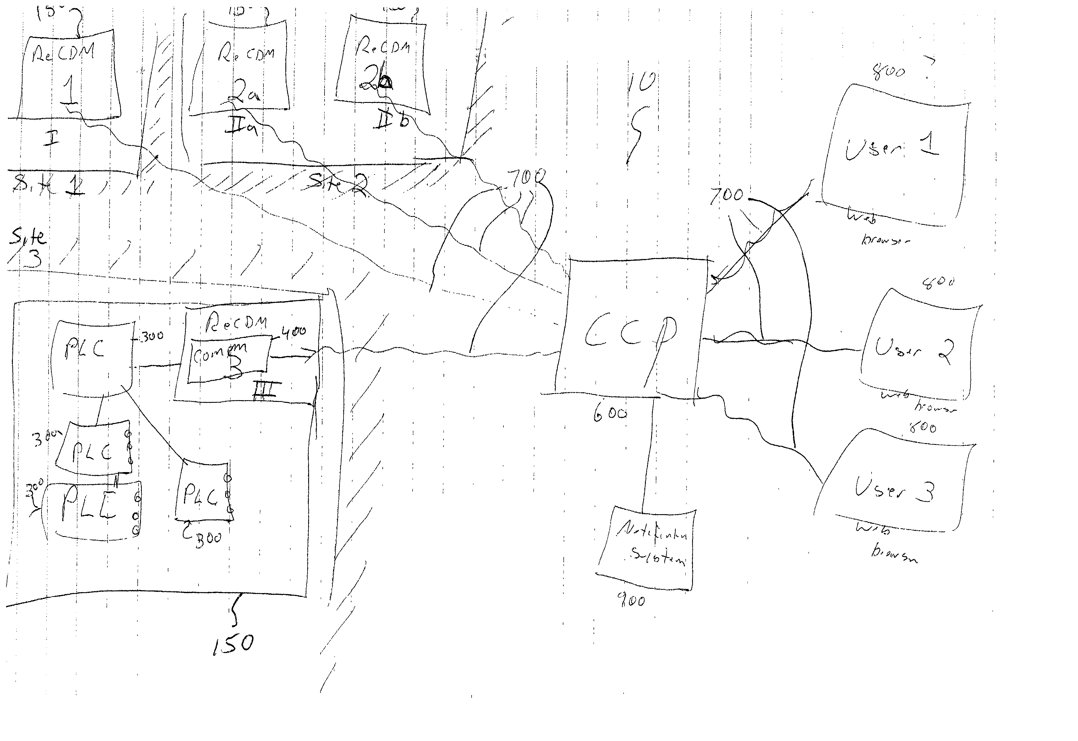
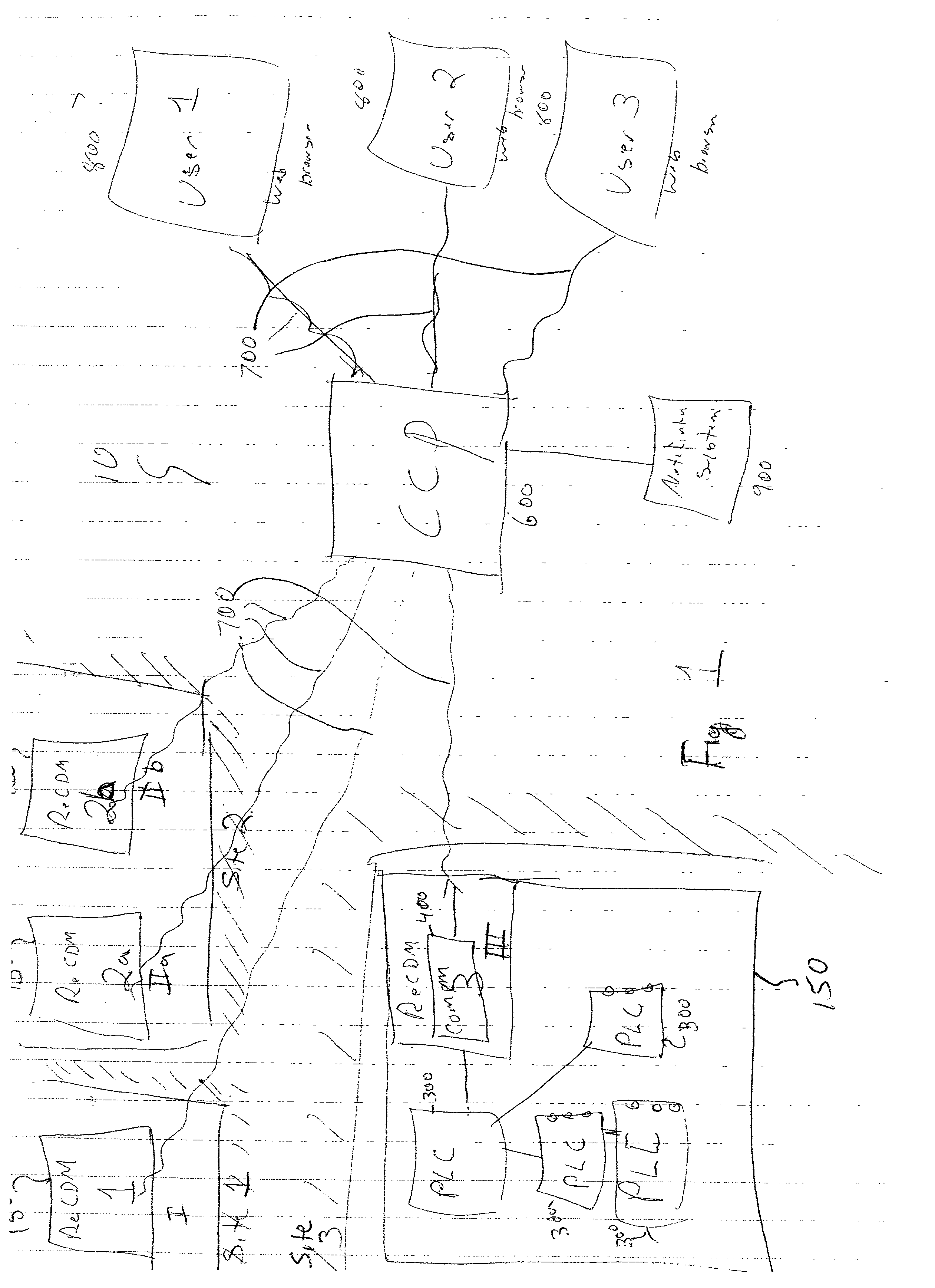
[0124] The system and process of Example 2 are repeated except that a hyperlink, when selected, sends instructions to the CCP 600 to initiate a script or program which sends a command to the EDMC 150 to activate an output, resulting in a ventilation fan being turned on at the location of the EDMC 150. The CCP 600 will process any feedback signal from the EDMC 150 and redraw or update the web page to signify that the requested action was successful, changing the color of the hyperlink, for example.

example # 4

EXAMPLE #4

[0125] The system and process of Example 2 are repeated except that a hyperlink, when selected, can send instructions to the CCP 600 to initiate a script or program which sends a request to the EDMC 150 to request and send the value of a specified input (e.g., sensor). The CCP 600 will process the requested signal from the EDMC 150 and redraw or update the web page to signify the current value of the input, in readable format, temperature in Degrees Fahrenheit, for example.


PUM


Abstract

A plurality of self-contained remote environmental data-monitor-control units communicate with a central collection point, including transmitting and receiving data, control signals, program parameters and alert signals. The central collection point includes a web page interface allowing end users to view real-time, current status as well as trended data in textual or graphical form. The central collection point processes and forwards alert signals received from a remote environmental data-monitor-control unit or a third-party monitoring system to an alert notification system which can accept alert signals via email, page, and direct point-to-point communication, processes the alert signal to verify validity and eliminate redundant signals, and notifies one or more pre-selected recipients of the condition which caused the alert via confirmable, person-to-person notification.

Description

[0001] This application claims priority from U.S. Provisional Application No. 60 / 205,696, filed May 19, 2000, the entire disclosure of which is hereby incorporated by reference.[0002] 1. Field of the Invention[0003] This invention relates generally to monitoring devices. In particular, the invention encompasses a method and system for monitoring the status of one or more systems at one or more sites and collecting and processing the status data, in real-time, at a remote centralized location. A person-to-person notification can be initiated from the remote centralized location upon the occurrence of certain conditions of a monitored system. Communication between the monitored system and the central collection location may be via a suitable wireless communication medium, a wired connection, or any industry standard protocol for communication.[0004] The system also provides for a remote user to be able to: control the monitored system, program monitoring and control parameters at the ...

Claims


Application Information

Patent Timeline
IPC IPC(8): H04L12/24H04L12/26H04M11/00H04M11/04
CPCH04L41/0604H04L41/0681H04M11/04H04M11/002H04L41/22
Inventor ALEXANDER, WADE H. IIIDICKINSON, JOHN D. JR.
Owner ALEXANDER WADE H III
Why Eureka
Try Eureka