

Catheter assemble
a catheter and assembly technology, applied in the field of catheter assembly, can solve the problems of inability to fully treat the patient, inducing internal bleeding, and provoking withdrawal action
- Summary
- Abstract
- Description
- Claims
- Application Information
AI Technical Summary
Benefits of technology
Problems solved by technology
Method used
Image

Examples
first embodiment
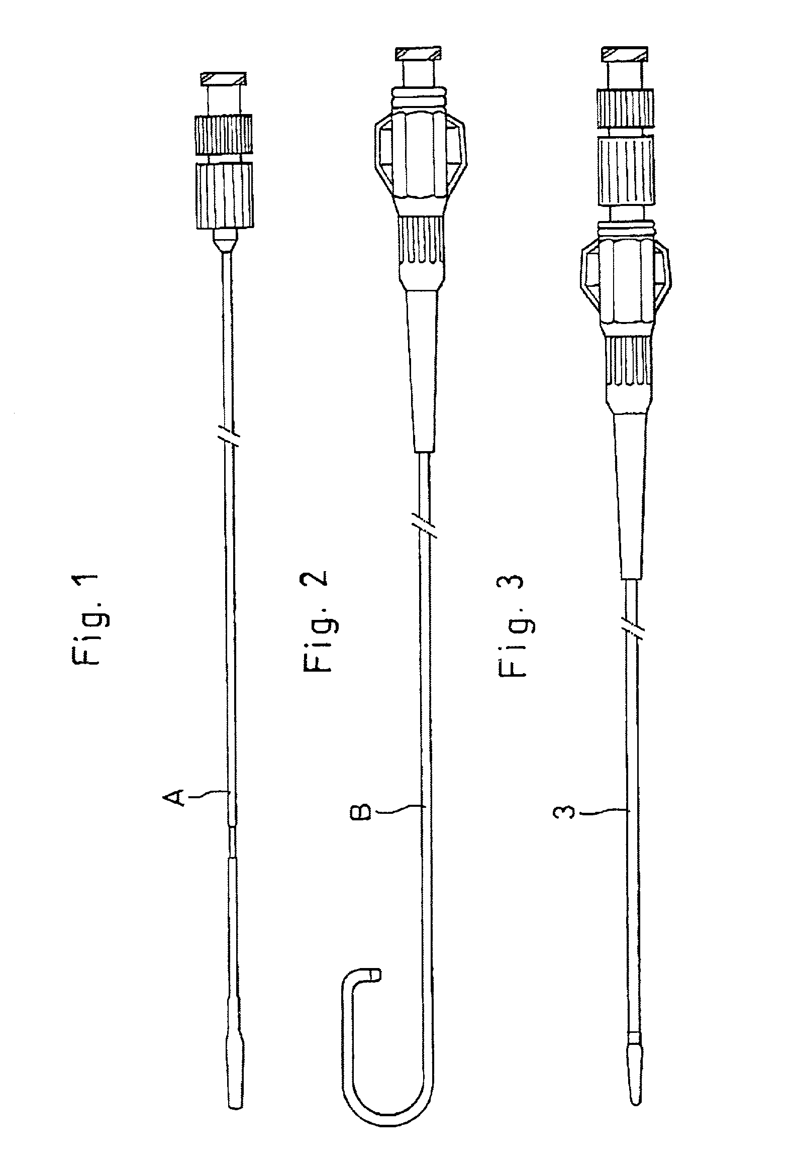
[0049] Referring to FIGS. 1 through 8 which show the invention, FIGS. 1, 2 and 3 in turn depict an introducing catheter (A), a tubular diagnostic-therapeutic catheter (B) and an assemble of the introducing catheter (A) and the diagnostic-therapeutic catheter (B).
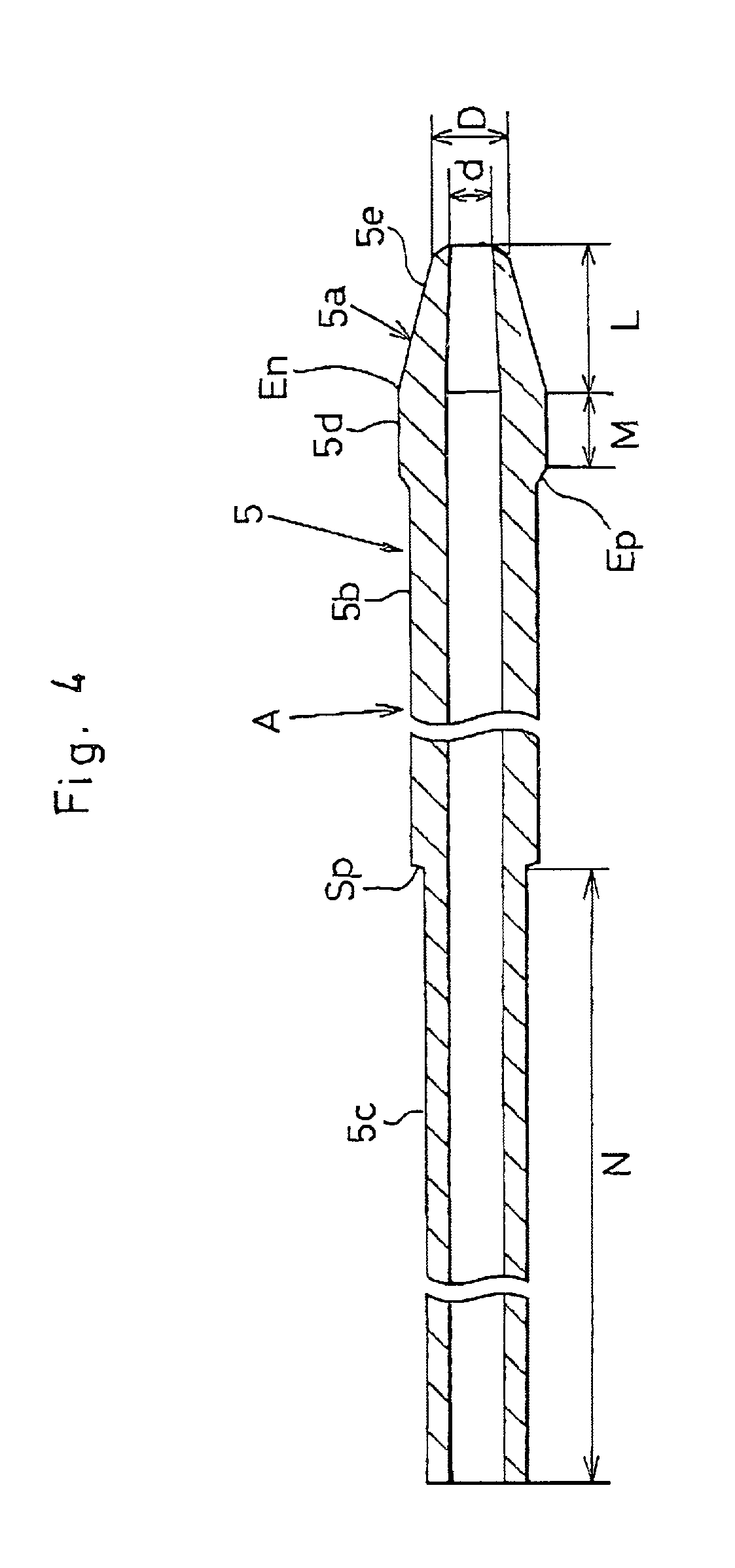
[0050] A distal portion of the introducing catheter (A) has a tubular shaft portion 5 as shown in FIGS. 4 and 5. A front end 5a of the shaft portion 5 has a cone-shaped section 5e, a quasi-linear section 5d and a stepped section (Ep). The cone-shaped section 5e is tapered off (within a range of 1.about.60 degrees, preferably 5.about.30 degrees) toward the front end of the shaft portion 5.
[0051] A linear section 5b (0.3.about.3.3 mm, preferably 1.0.about.2.4 mm in dia.) contiguous with the quasi-linear section 5d is thinner than the quasi-linear section 5d.
[0052] The front end 5a is 5.about.40 mm in length (L), 0.2.about.1.5 mm in inner diameter (d) and 0.3.about.2.0 mm in outer diameter (D). The quasi-linear section 5d measu...
second embodiment
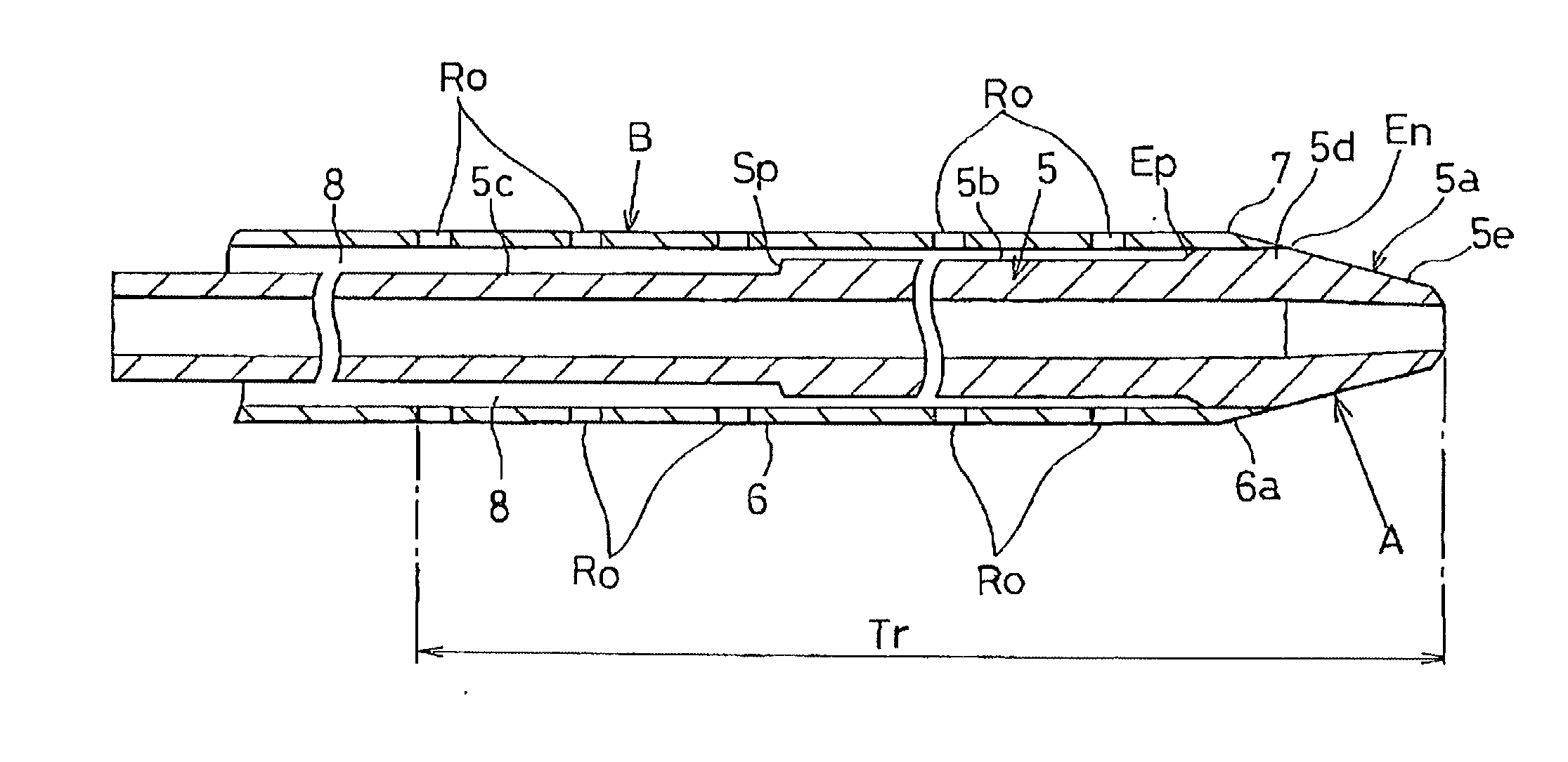
[0084] FIG. 9 shows the invention in which the diagnostic-therapeutic catheter (B) has a plurality of drug-releasable side holes (Ro) extending by approx. 20 cm from the front end of the shaft portion 5 to a near proximal end portion as depicted at a distance (Tr) in FIG. 9.
[0085] The drug-releasable side holes (Ro) are in communication with the annular space 8 between the diagnostic-therapeutic catheter (B) and the introducing catheter (A). Each diameter of the drug-releasable side holes (Ro) is determined to be 1.5 mm or less (preferably 30.about.100 m.mu.) to prevent the contrast agent from inadvertently leaking out when supplying the contrast agent to the diagnostic-therapeutic catheter (B).
[0086] The anti-spasmodic drug is injected into the annular space 8 to supply it through the drug-releasable side holes (Ro) to cure the spasm which the diagnostic-therapeutic catheter (B) sent into the radial artery (V).
[0087] In this instance, the distal end 7 tightly engages with the taper...
third embodiment
[0089] FIGS. 10 through 12 show the invention in which the front end section 6a of the shaft portion 5 has a bight portion (W). The bight portion (W) has a front inner edge 6m, a circumferential length of which is rounded rearward by a quarter (1 / 4) or less.
[0090] Namely, a quarter (1 / 4) or less of a circular cross section of the front inner edge 6m is shaved back from a distal end toward the front end section 6a as shown in FIGS. 10 and 11.
[0091] The front inner edge 6m comes to form a wider surface area (Sq) as shown in FIG. 11. The front inner edge 6m is in surface contact with the coronary artery to effectively prevent the injury against the blood vessel wall (FIG. 12) as opposed to the prior art (FIG. 13) in which a sharp edge of the catheter (Ka) encounters the entry of the coronary artery (point-to-point contact) so as to injure or dissociate the blood vessel's endothelio.
[0092] When the circumferential length of the inner edge 6m is rounded rearward by more than a quarter (e...
PUM
| Property | Measurement | Unit |
|---|---|---|
| size | aaaaa | aaaaa |
| Shore hardness | aaaaa | aaaaa |
| OD | aaaaa | aaaaa |
Abstract
Description
Claims
Application Information