
Wavelength multiplexed quantitative differential interference contrast microscopy

a contrast microscope and multi-wavelength technology, applied in the field of differential interference contrast microscope systems, can solve the problems of small loss in precision, large amount of data generated by the wai microscope, and significant differences between the microscopes, and achieve rapid, robust, and robust measurement of the slope of the sample surfa

Inactive Publication Date: 2002-07-11
KUHN WILLIAM P
View PDF0 Cites 24 Cited by
  • Summary
  • Abstract
  • Description
  • Claims
  • Application Information

AI Technical Summary

Benefits of technology

[0023] The various approaches disclosed and claimed herein permit rapid, robust measurement of slope in two directions. A DIC microscope is insensitive to the environment, unlike other interference microscopes; however, slope data in two directions are necessary to determine, via integration, the surface shape, rather than just a height profile of the surface. The various approaches disclosed and claimed herein permit rapid, robust measurement of sample surface slope in two directions.
[0042] FIG. 9 depicts a modification to the DFOV optics and objective to maximize the use of available light;

Problems solved by technology

The practical difference between the two types of microscopes is that a WLI microscope generates large amounts of data and uses substantially different processing algorithms to obtain a much greater measurement range than phase-shifting microscopes, with only a modest loss in precision.
However, both microscopes share a significant problem--extreme sensitivity to environmental effects, especially vibration and air turbulence.
There are two difficulties with using an interferometer that produces slope fringes.
First, slope fringes are difficult to visually interpret and second, slope must be measured in two directions to fully reconstruct a surface.
In modem manufacturing processes, visual inspection of images is avoided not only because it is slower but also because it is less reliable, precise and accurate than automated image processing.
A major limitation of a DIC microscope as compared to a WLI microscope is the need, in general, for rapid, robust measurement of slope in two directions.

Method used


Image

  • Wavelength multiplexed quantitative differential interference contrast microscopy
  • Wavelength multiplexed quantitative differential interference contrast microscopy
  • Wavelength multiplexed quantitative differential interference contrast microscopy

Examples


Embodiment Construction

[0045] Reference is now made in detail to a specific embodiment of the present invention, which illustrates the best mode presently contemplated by the inventor for practicing the invention. Alternative embodiments are also briefly described as applicable.

[0046] 1. DIC Background.

[0047] The advantage of DIC measurement methods over typical interferometric microscopes is due to common path design of the interferometer and resultant insensitivity to vibration and other environmental effects. However, the data obtained by DIC measurements represents surface slope rather than surface height. Additionally, it is necessary to measure slope in two directions and integrate to permit the unambiguous determination of height a general surface. It is preferable that the slope data are in two orthogonal directions; however, the requirement is that the directions are not parallel.

[0048] Hong et al, in section 3 of their above-referenced paper, describe how to obtain height profiles in one directi...


PUM


Abstract

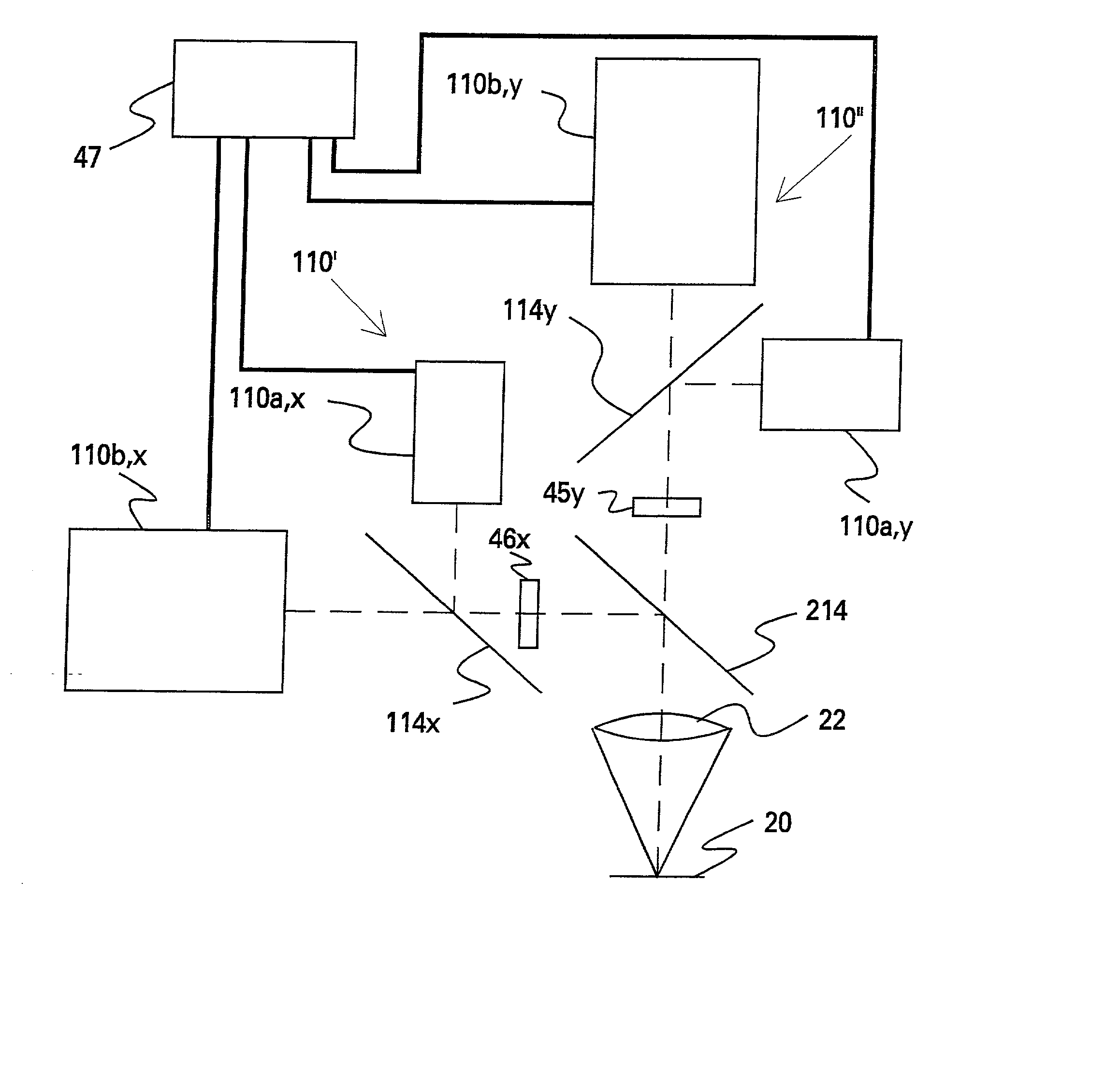
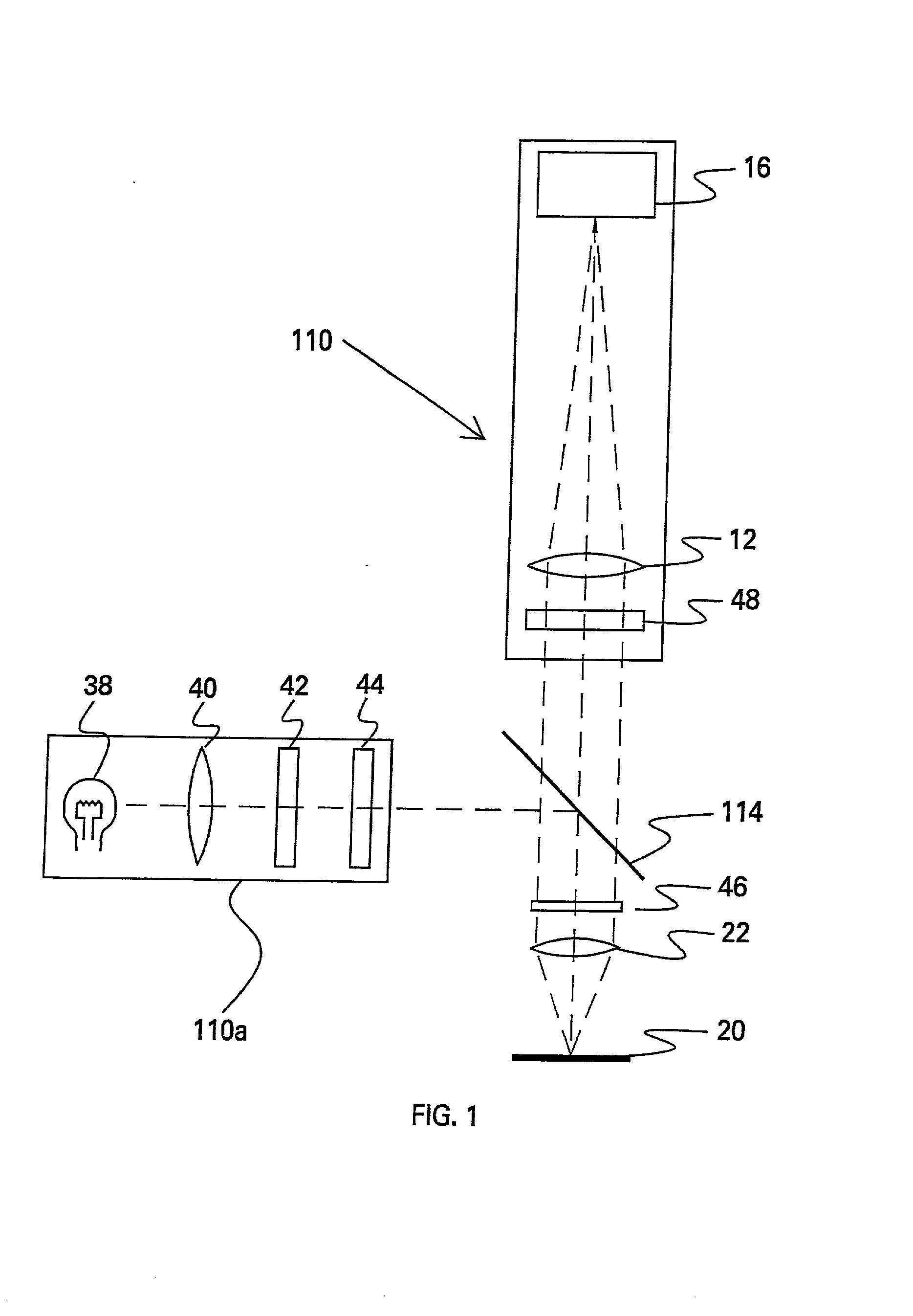
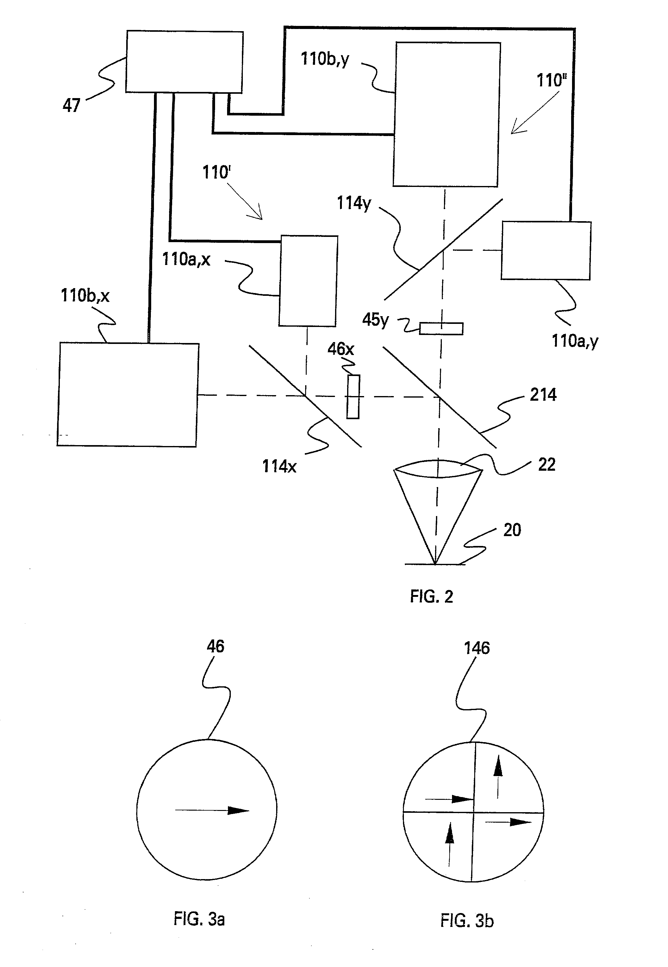
A differential interference contrast (DIC) microscope system is provided comprising: (a) an illumination source for illuminating a sample ; (b) a lens system for viewing the illuminated sample, including an objective, defining an optical axis; (c) at least one detector system for receiving a sample image; (d) mechanisms for wavelength multiplexing the shear direction or shear magnitude or both on the sample and demultiplexing the resultant DIC images on the detector; and (e) a mechanism for modulating the phase of the interference image. Various approaches are disclosed to accomplish wavelength multiplexing of shear direction and demultiplexing the two DIC images that result. It is possible for the two, wavelength multiplexed DIC images to differ in either or both shear direction or magnitude. These approaches include (1) two DIC microscopes, each operating at a different wavelength, but which share a single objective through a beam splitter; (2) a segmented DIC prism that is made in four sections where opposite sections are paired and have the same shear direction and amount, and each pair of sections have filters transmitting different wavelengths; (3) a segmented DIC prism that is located in or near an aperture stop or pupil of said DIC microscope to obtain data in two shear directions that is multiplexed by wavelength; (4) a dual field-of-view optical system with two DIC prisms, one in each path to wavelength multiplex shear direction or shear magnitude through said objective; (5) demultiplexing wavelength multiplexed DIC images through the use of a wavelength selective beam splitter and two detectors; (6) demultiplexing wavelength multiplexed DIC images through the use of a wavelength controlled source and a single detector; and (7) demultiplexing wavelength multiplexed DIC images through the use of dual field-of-view optics and a single detector. These various approaches permit rapid, robust measurement of slope in two directions. Further, phase shifting and DIC microscopy are limited to measurements within the depth of focus (DOF) of the objective while WLI microscopy is not.

Description

[0001] The present application is a non-provisional application, and claims priority based on provisional application Ser. No. 60 / 137,061, filed on Jun. 1, 1999.[0002] The present application is related to application Ser. No______. filed on even date herewith [D-99025B]. That application is directed to how to increase the effective wavelength of a DIC measurement and thereby increase the slope of a surface that can be measured without ambiguity by combining data taken at two or more wavelengths or two or more shear distances. The present application is also related to application Ser. No.______, also filed on even date herewith [D-99025C]. That application is directed to extending the range of a quantitative DIC microscope to permit the measurement of samples having height variations greater than the depth of focus (DOF) of an objective.[0003] The present invention is directed generally to optical microscopy and in particular addresses the need to obtain efficiently, quantitative s...

Claims


Application Information

Patent Timeline
Patent Type & Authority Applications(United States)
IPC IPC(8): G01B9/04G02B21/00G02B21/14G02B21/18
CPCG01B9/04G02B21/14G02B21/18
Inventor KUHN, WILLIAM P.
Owner KUHN WILLIAM P
Learn More