Electromagnet and actuating mechanism for switch device, using thereof

a technology of actuating mechanism and switch device, which is applied in the direction of contact mechanism, magnets, magnetic bodies, etc., can solve the problems of metric errors caused during manufacture, relative high manufacturing cost, and the thickness of permanent magnet and the core is inevitabl

Inactive Publication Date: 2002-07-18
HITACHI IND EQUIP SYST CO LTD
View PDF9 Cites 52 Cited by
  • Summary
  • Abstract
  • Description
  • Claims
  • Application Information

AI Technical Summary

Problems solved by technology

These mechanism have a large number of components so as to have a link mechanism which is complicated, resulting in a relatively high manufacturing cost.
However, the conventional electromagnet incorporating a permanent magnet has raised following disadvantages: a permanent magnet may be a rare-earth samarium cobalt group magnet, a neodymium group magnet, an alnico group magnet, a ferrite group magnet or the like.
Accordingly, it is unpractical to magnetize a permanent magnet with a coil of an incorporated electromagnet, and accordingly, a magnet has to be incorporated after being magnetized.
The repetition of appl

Method used


Image

  • Electromagnet and actuating mechanism for switch device, using thereof
  • Electromagnet and actuating mechanism for switch device, using thereof
  • Electromagnet and actuating mechanism for switch device, using thereof

Examples


embodiment 1

[0039] (Embodiment 1)

[0040] Explanation will be made of a first embodiment of the present invention with reference to FIGS. 1 to 5.

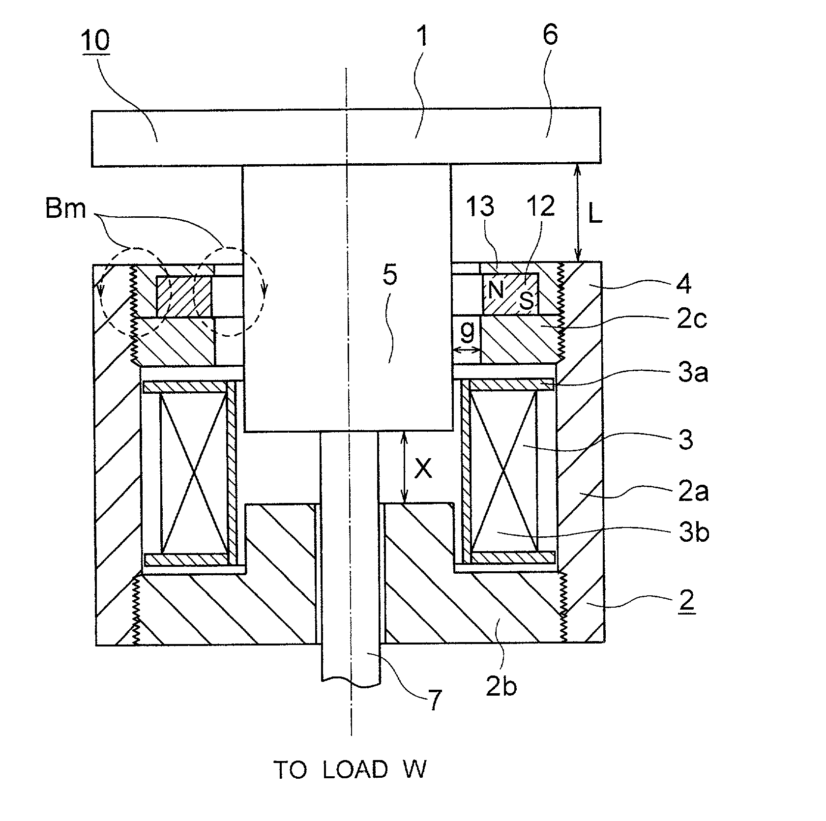
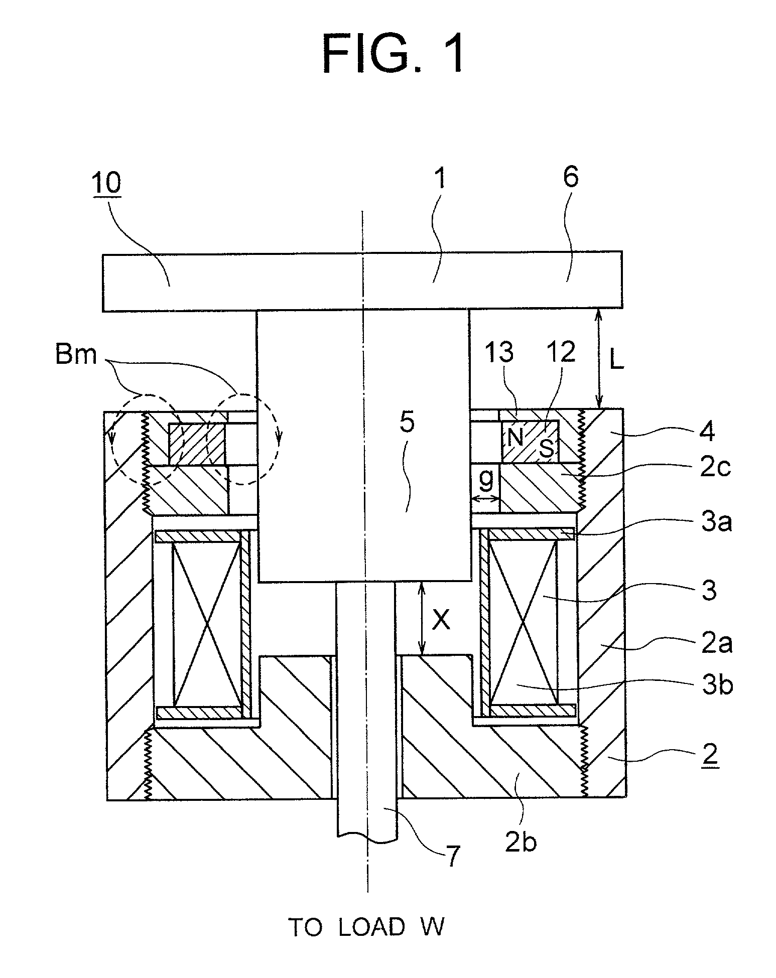
[0041] Referring to FIG. 1 which is a sectional view illustrating an electromagnet 10 in the first embodiment of the present invention, the electromagnet 10 has an axially symmetric structure. In this figure, reference numerals are attached to elements shown on the right half of the figure for explaining the structure of the electromagnet 10, and a magnetic field B (indicated by the chain line) which is effected by a permanent magnet 12 and current running through a coil 3 is shown in the left half of the figure.

[0042] A movable core 1 is composed of a plunger 5 extending through the coil on the center axis thereof, and a dick-like steel plate 6 secured to one end part of the plunger 5, and is coupled to a load W by means of a nonmagnetic coupling member 7 secured to an end part of the plunger 5. The load W effects a force which urges the movable iron co...

embodiment 2

[0052] (Embodiment 2)

[0053] Explanation will be made of a second embodiment with reference to FIGS. 6 and 7.

[0054] FIG. 6 is a sectional view illustrating an electromagnet 10 in a second embodiment of the present invention. A movable iron core 1 is composed of a plunger 5 extending through a coil 3 along the center axis of the latter, and a disc-like steel plate 6 secured to one end part of the plunger, and is coupled to a load through the intermediary of a nonmagnetic coupling member 7 secured to the other end part of the plunger 5. A stationary iron core 2 is composed of a steel pipe 2a, a convex steel member 2b and a ring-like steel plate 2c which are all magnetic. The convex steel member 2b and the ring-like steel plate 2c may be attached to the opposite ends of the steel pipe 2a, being screwed thereinto. Alternatively, they may be secured thereto by welding. The convex steel member 2b may be manufactured in one unit body, but it may be formed of two steel plates connected to ea...

embodiment 3

[0064] (Embodiment 3)

[0065] Explanation will be hereinbelow made of a third embodiment of the present invention with reference to FIGS. 9 (in a turn-on condition) and 10 (in a turn-off condition). FIGS. 9 and 10 are sectional views illustrating an electromagnet 10 in this embodiment, when a switching device which is coupled to the electromagnet is turned on (FIG. 9) and when the switching device which is coupled to the electromagnet is turned off (FIG. 10), respectively. The turn-on condition and the turn-off condition, which will be taken in the following description, are conditions of the electromagnet obtained when the switching device which is coupled to the electromagnet is turned on and off, respectively.

[0066] The coil 3 is composed of a bobbin 3a made of an insulator or nonmagnetic metal (aluminum, copper or the like), and windings 3b.

[0067] The electromagnet 10 as shown is composed of the coil 3, a movable iron core adapted to be moved on the center axis of the coil 3 and m...


PUM


Abstract

An electromagnet composed of a coil, a movable iron core adapted to move on the center axis of the coil, and a stationary iron core provided so as to cover the upper and lower surfaces and the outer peripheral surface of the coil, characterized by a permanent magnet arranged in a gap surrounded by the movable iron core and the stationary core, wherein the movable iron core is attracted by the stationary iron core by a magnetic field created by the permanent magnet, thereby it is possible to solve a problem inherent to a conventional electromagnet such that a permanent magnet is directly energized in a reverse direction during release operation so as to cause demagnetization of the permanent magnet. That is, since the permanent magnet is arranged in the gap surrounded by the movable iron core and the stationary iron core, the magnetic filed can be prevented from affecting upon the permanent magnet, thereby it is possible to provide an electromagnet having a long use like and a high degree of reliability with no demagnetization of a permanent magnet.

Description

[0001] The present invention relates to an electromagnet and as well to an actuating mechanism using thereof for a switching device, and in particular to an electromagnet for restraining demagnetization of a permanent magnet, and as well to a reliable operating mechanism using thereof for a switching device.[0002] 1. Related Art[0003] As to the actuating mechanism for a switching device, there have been provided an electric power driven spring actuating mechanism, and a hydraulic or pneumatic actuating mechanism. These mechanism have a large number of components so as to have a link mechanism which is complicated, resulting in a relatively high manufacturing cost. An operating mechanism using an electromagnet is used as one of measures for simplifying the link mechanism. For example, JP-A-5-234475 discloses a vacuum contactor in which an electromagnet is used for turn-on operation so that a closing spring which has been stored with energy is released simultaneously with the turn-on ...

Claims


Application Information

Patent Timeline
IPC IPC(8): H01H33/666H01H51/22
CPCH01F7/122H01F7/1615H01F7/1623H01H33/6662H01H51/2209
Inventor MORITA, AYUMUSUZUKI, YASUAKIYABU, MASATOTANIMIZU, TOORUSHIBATA, YOZOKADOWAKI, TAKASHI
Owner HITACHI IND EQUIP SYST CO LTD
Why Eureka
Try Eureka