Methods and apparatus for transpericardial left atrial appendage closure

a technology of left atrial appendage and transpericardial valve, which is applied in the field of medical methods and equipment, can solve the problems of increasing the risk of injuring the hear

Inactive Publication Date: 2002-07-25
SENTREHEART LLC
View PDF99 Cites 174 Cited by
  • Summary
  • Abstract
  • Description
  • Claims
  • Application Information

AI Technical Summary

Benefits of technology

[0019] A variety of specific instruments, devices, and systems may be devised for performing the methods of the present invention. An exemplary device for closing a left atrial appendage according to the methods of the present invention is described in detail in the descriptions that follow. The device comprises a shaft having a proximal end and a distal end, where the distal end is adapted to percutaneously enter the pericardial space, be advanced over an epicardial surface, and then approach the exterior of the left atrial appendage. Preferably, the shaft has a length in the range from 10 cm to 40 cm, a width in the range from 2 mm to 20 mm, and a thickness in the range from 1 mm to 10 mm. Usually, the shaft will be curved over its length to be compatible with the curvature of the heart. The shaft may include a means to alter the curvature to accommodate variations in anatomy. Similarly, the device may preferably include a crescent-shaped cross-section to also conform to the shape of the exterior of the heart. The device will carry a mechanism or means for closing the left atrial appendage when the distal end of the shaft is positioned adjacent to the appendage. Usually, the closure mechanism will be introducable through one or more lumens formed in the shaft. In a particularly preferred configuration, the distal end of the shaft will be configured to lie within the atrioventricular groove of the heart, and at least one lumen through the shaft will have an exit port spaced inwardly from the distal end of the shaft by a distance in the range from 0.5 cm to 5 cm. In this way, the port will be positioned properly to access the free end of the atrial appendage for performing the closing procedures. In addition, the shaft may have one or more additional lumens (for a total of two, three, or more lumens through the shaft) in order to provide additional capabilities, including introduction and use of a viewing scope, infusion and perfusion of fluids, particularly the infusion of saline to facilitate viewing. Optionally, the lumens can be used to introduce an anesthetic agent, such as lidocaine, in order to reduce pain or to introduce an anti-arrhythmic agent to reduce myocardial irritability.

Problems solved by technology

Use of a trocar and cannula may be less preferred, however, since there is an increased risk of injuring the heart if the trocar and cannula assembly is introduced in a blind fashion.

Method used


Image

  • Methods and apparatus for transpericardial left atrial appendage closure
  • Methods and apparatus for transpericardial left atrial appendage closure
  • Methods and apparatus for transpericardial left atrial appendage closure

Examples


Embodiment Construction

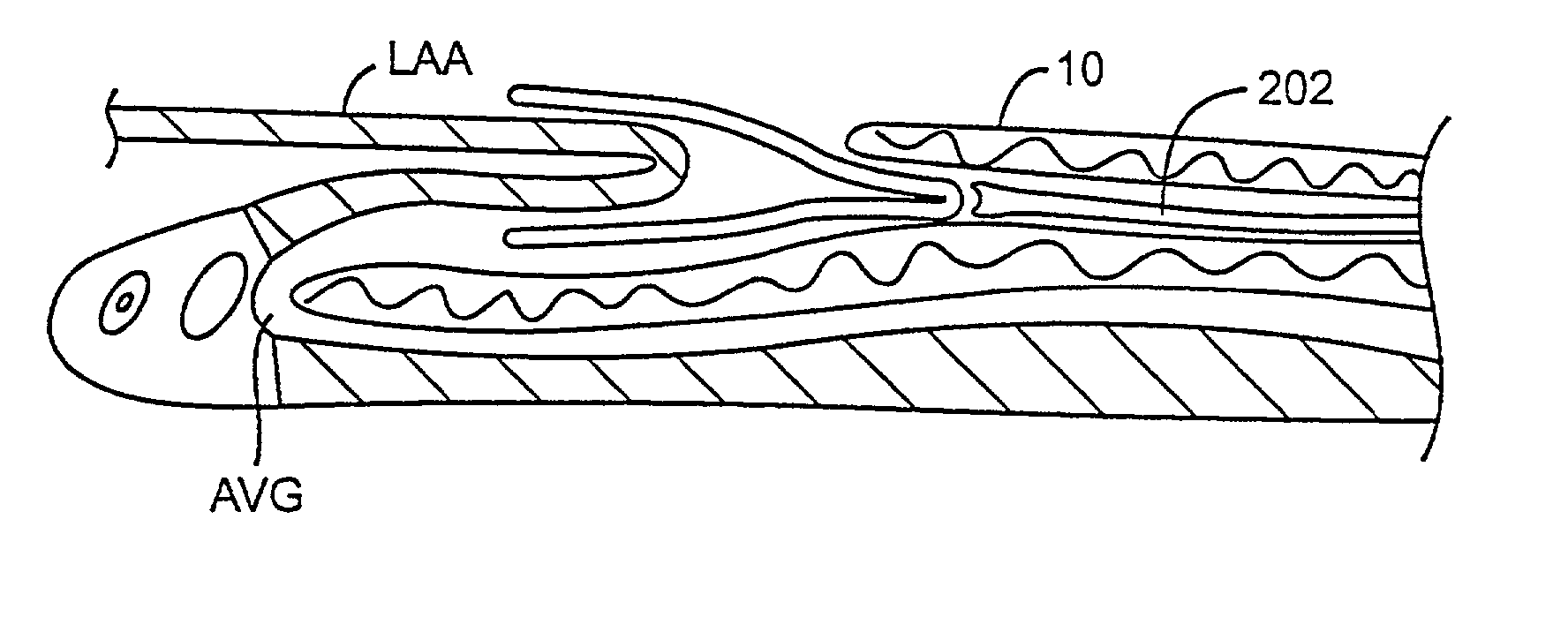
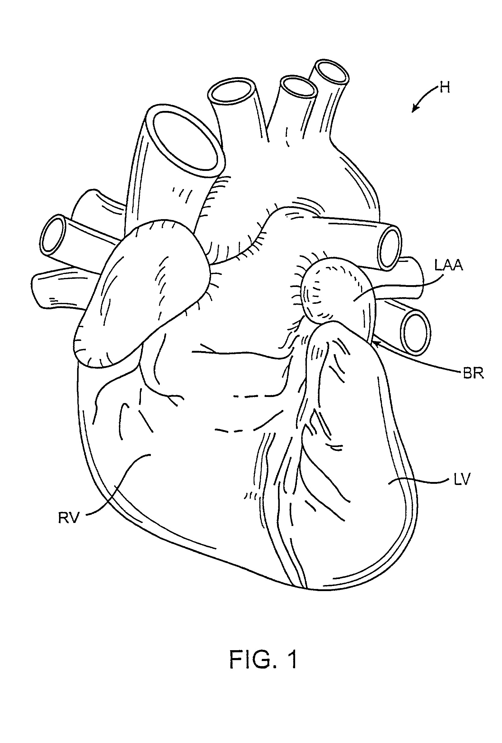
[0033] FIG. 1 is an anterior view of a heart illustrating the right ventricle RV, the left ventricle LV, and the left atrial appendage LAA. The methods and apparatus of the present invention are intended to place a closure structure over or otherwise close off the base region BR of the left atrial appendage. By closing off the base region BR, the exchange of materials between the left atrial appendage LAA and the left atrium LA will be stopped. Thus, the release of emboli from the left atrial appendage into the left atrium will be stopped.

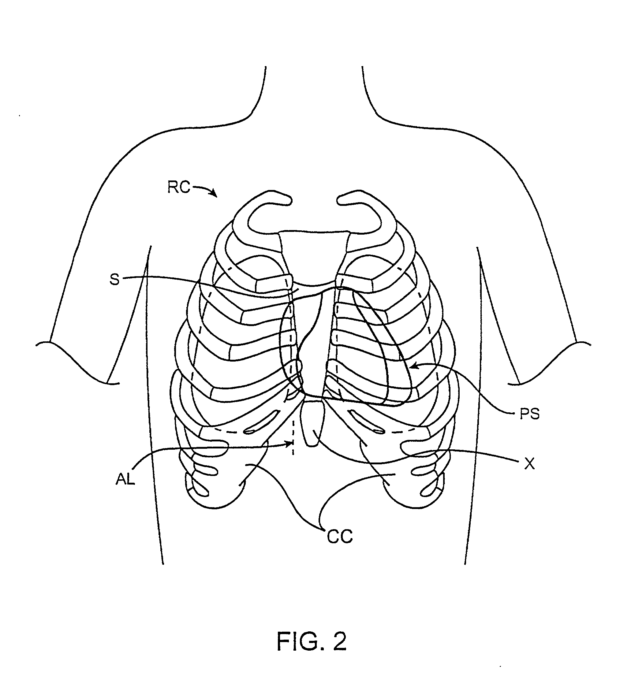
[0034] Referring now to FIG. 2, the heart is located within the pericardial space PS located beneath the patient's rib cage RC. The sternum S is located in the center of the rib cage RC and terminates at its lower end in the xiphoid X. On either side of the xiphoid are the costal cartilage CC, and the percutaneous access points for performing the procedures of the present invention will be located beneath the rib cage RC, and preferably between the...


PUM


Abstract

Methods and apparatus for closing a left atrial appendage are described. The methods rely on introducing a closure tool from a location beneath the rib cage, over an epicardial surface, and to the exterior of the left atrial appendage. The closure device may then be used to close the left atrial appendage, preferably at its base, by any one of a variety of techniques. A specific technique using graspers and a closing loop is illustrated.

Description

[0001] 1. Field of the Invention[0002] The present invention relates generally to medical methods and apparatus. More particularly, the present invention relates to a method and device for the minimally invasive closure of a left atrial appendage of the heart.[0003] Atrial fibrillation is a common cardiac rhythm disorder affecting a population of approximately 2.5 million patients in the United States alone. Atrial fibrillation results from a number of different causes and is characterized by a rapid chaotic heart beat. In addition to the risks associated with a disordered heart beat, patients with atrial fibrillation also have an increased risk of stroke. It has been estimated that approximately 75,000 atrial fibrillation patients each year suffer a stroke related to that condition. It appears that strokes in these patients result from emboli many of which may originate from the left atrial appendage. The irregular heart beat causes blood to pool in the left atrial appendage, allow...

Claims


Application Information

Patent Timeline
Patent Type & Authority Applications(United States)
IPC IPC(8): A61B17/00A61B17/12A61B17/122A61B17/128
CPCA61B17/10A61B17/12A61B17/12013A61B2017/320048A61B17/1285A61B2017/00243A61B17/122
Inventor KAPLAN, AARON V.BAJOR, JORDON T.
Owner SENTREHEART LLC
Why Eureka
Try Eureka