Tissue-based water quality biosensors for detecting chemical warfare agents

a biosensor and tissue technology, applied in the field of indigenousphotosynthetic tissue biosensors for detecting chemical and biological warfare agents, can solve the problems of serious sensor fouling, unpractical remote, continuous monitoring, etc., and achieve the effect of reducing fluorescence and reducing photosynthetic capability

Inactive Publication Date: 2002-08-01
UT BATTELLE LLC
View PDF0 Cites 18 Cited by
  • Summary
  • Abstract
  • Description
  • Claims
  • Application Information

AI Technical Summary

Benefits of technology

0036] As water samples are passed through the cell, any component of the water that negatively impacts photosynthetic capability will cause a change in the fluorescence induction curve, with resultant changes in the quantum yield of fluorescence. As described in further detail below, the change in fluorescence represents a decrease in photosynthetic capability. Different chemical warfare agents will have different influences on the photosynthetic apparatus of a particular alga or cyanobacterium. And the same chemical agent will affect the fluorescence of different organisms in different ways. Some will cause an increase, while others will cause a decrease in fluorescence (non-photochemical quenching of fluorescence). Specific antagonists combined with specific algae or cyanobacteria will cause characteristic changes that can be used to construct a look-up library or database of cause and effect combinations.

Problems solved by technology

A disadvantage of a system using entrapped algae is that fouling of the sensor is a serious problem since the instrument is useless after such fouling until a new sensor is installed.
This is not practical for remote, continuous monitoring.

Method used


Image

  • Tissue-based water quality biosensors for detecting chemical warfare agents
  • Tissue-based water quality biosensors for detecting chemical warfare agents
  • Tissue-based water quality biosensors for detecting chemical warfare agents

Examples


example ii

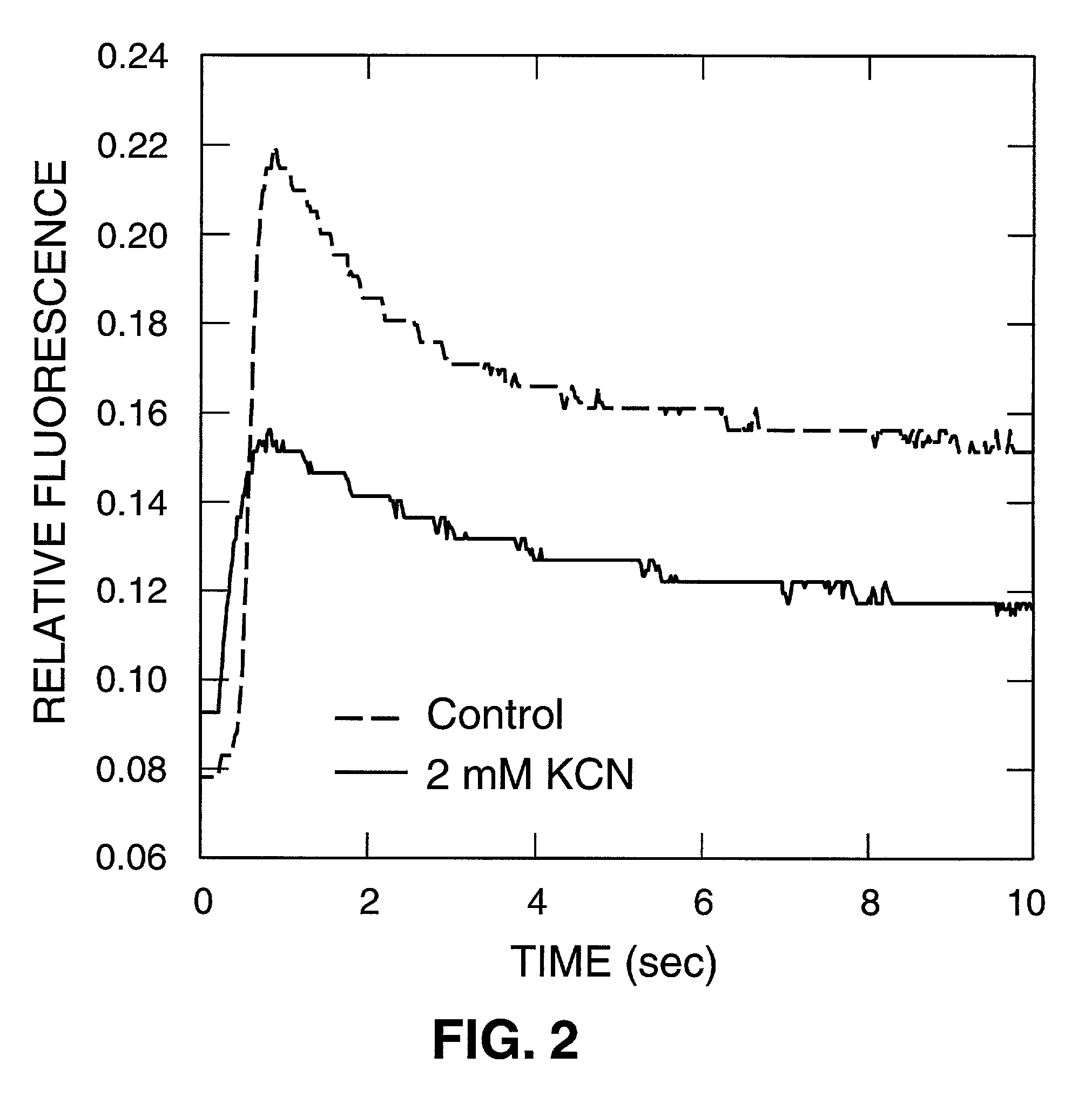
[0041] FIG. 2 is an illustration of the detection of potassium cyanide (KCN), a well known poison. The experimental protocol was similar to that of Example I above. Control and sample fluorescence curves are illustrated. Six minutes after exposure of the sample to a 2 mM final concentration of KCN, a clear difference between control and sample can be observed, including a widening of the maximal fluorescence peak (P) in the KCN curve that indicates slower fluorescence quenching after maximal fluorescence has been reached. The F.sub.o and F.sub.max values are altered as well. This fluorometric sensing technique can detect cyanide at concentrations below the minimum level for human toxicity.

example iii

[0042] The effect of herbicide 3-(3,4-dichlorophenyl)-1,1-dimethylurea (DCMU) on the water sample fluorescence induction curve was tested in a manner similar to Example I above. When DCMU was added to the cuvette, fluorescence increased considerably and was accompanied by a dramatic change in kinetic time course. A test fluorescence curve (FIG. 3) was recorded after a 6-minute exposure using a final concentration of 10 .mu.M DCU.

[0043] A simple biosensor 10 for carrying out the method of present invention is shown schematically in FIG. 4. A fluorometer 12 is attached to a cell 14 so that a cell window 16 faces the fluorometer input 18. The cell has an inlet 20 having an optional particulate filter 36 and an outlet 26 for passing water therethrough. A pump 24 draws water from the outlet 26 and expels same through an exit 28. The cell 14 could have a displacement pump which draws water into the cell and expels same through a common inlet / outlet opening (analogous to 20), obviating out...


PUM

PropertyMeasurementUnit
concentrationaaaaaaaaaa
chemicalaaaaaaaaaa
fluorescenceaaaaaaaaaa

Abstract

A method of testing water to detect the presence of at least one chemical or biological warfare agent includes the steps of: a. exposing water to a measuring means for measuring photosynthetic activity of free-living indigenous photosynthetic organisms; b. measuring photosynthetic activity of indigenous photosynthetic organisms occurring naturally in the water to detect the presence of at least one chemical or biological warfare agent in the water.

Description

[0001] This application claims the benefit of U.S. Provisional Application No. 60 / 226,646, filed on Aug. 21, 2000, the entire disclosure of which is incorporated herein by reference.[0003] The present invention relates to tissue-based sensors for detecting chemical and / or biological contaminants in water, and more particularly to sensors based on changes of quantum yield of fluorescence in which indigenous photosynthetic tissues that are naturally present in water are used as a sensor materials for detecting chemical and / or biological warfare agents in the water.[0004] Various sensors have been used to monitor water quality. Currently available water quality sensor technology is based generally on adaptations, modifications, and extensions of conventional analytical chemistry equipment and techniques. Some examples follow.[0005] U.S. Pat. No. 5,965,882 issued on Oct. 12, 1999 to Megerle et al. describes a miniaturized ion mobility spectrometer sensor cell that comprised an improved ...

Claims


Application Information

Patent Timeline
Patent Type & Authority Applications(United States)
IPC IPC(8): C12Q1/02G01N33/50
CPCC12Q1/02G01N33/5097G01N2520/00G01N2021/635
Inventor GREENBAUM, ELIASSANDERS, CHARLENE A.
Owner UT BATTELLE LLC
Why Eureka
Try Eureka