Valve comprising elastic sealing elements

a technology of elastic sealing elements and valves, which is applied in the field of valves, can solve the problems of complex assembly of individual components of valves, inconvenient assembly, and high cos

Inactive Publication Date: 2002-08-08
ROBERT BOSCH GMBH
View PDF0 Cites 16 Cited by
  • Summary
  • Abstract
  • Description
  • Claims
  • Application Information

AI Technical Summary

Problems solved by technology

A disadvantage of the valve described in DE 197 53 575 A1 and of all comparable valves is--for reasons of construction--the quite complex assembly of the individual components of the valve.
This described assembly is inc

Method used


Image

  • Valve comprising elastic sealing elements
  • Valve comprising elastic sealing elements
  • Valve comprising elastic sealing elements

Examples


Embodiment Construction

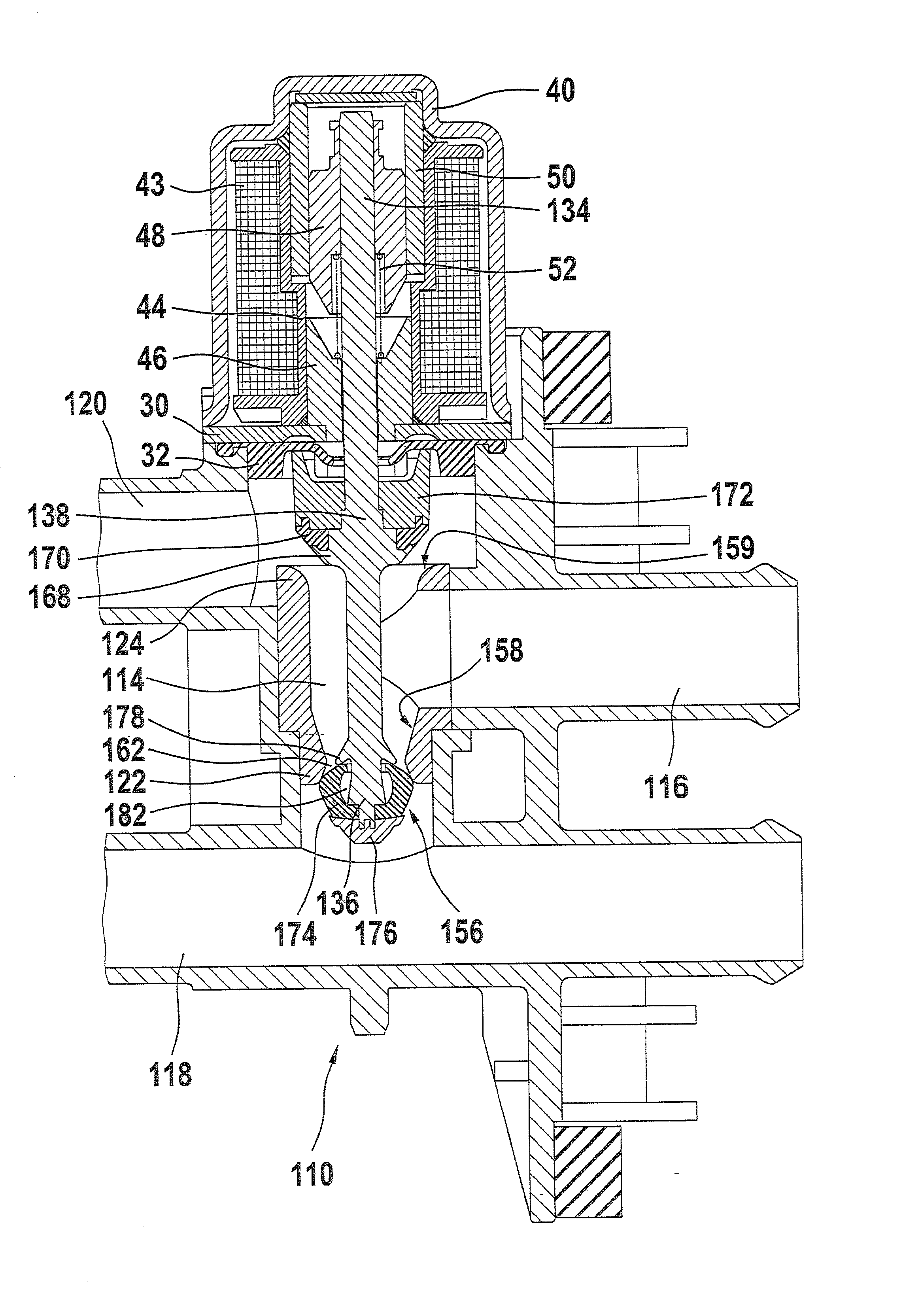
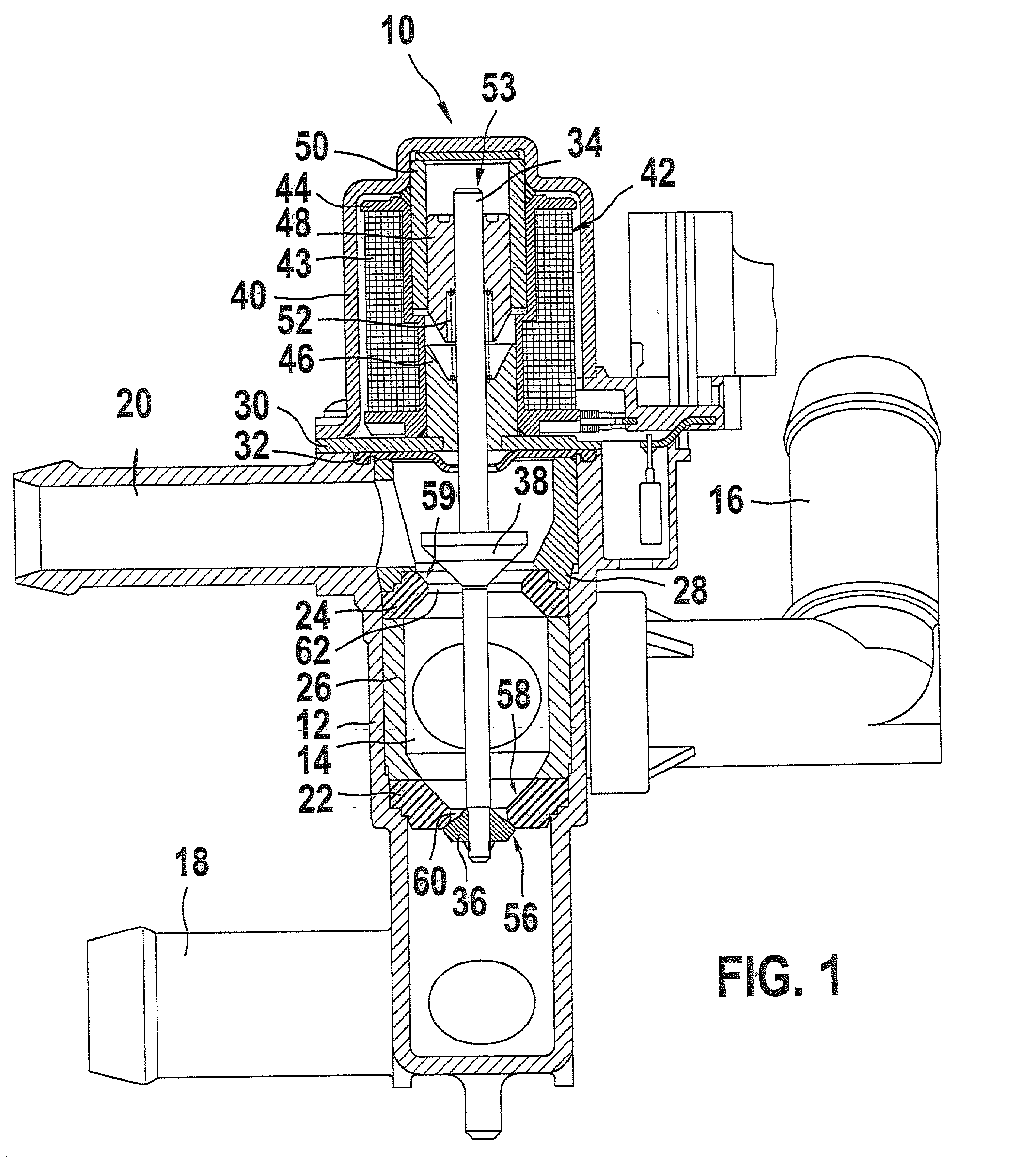
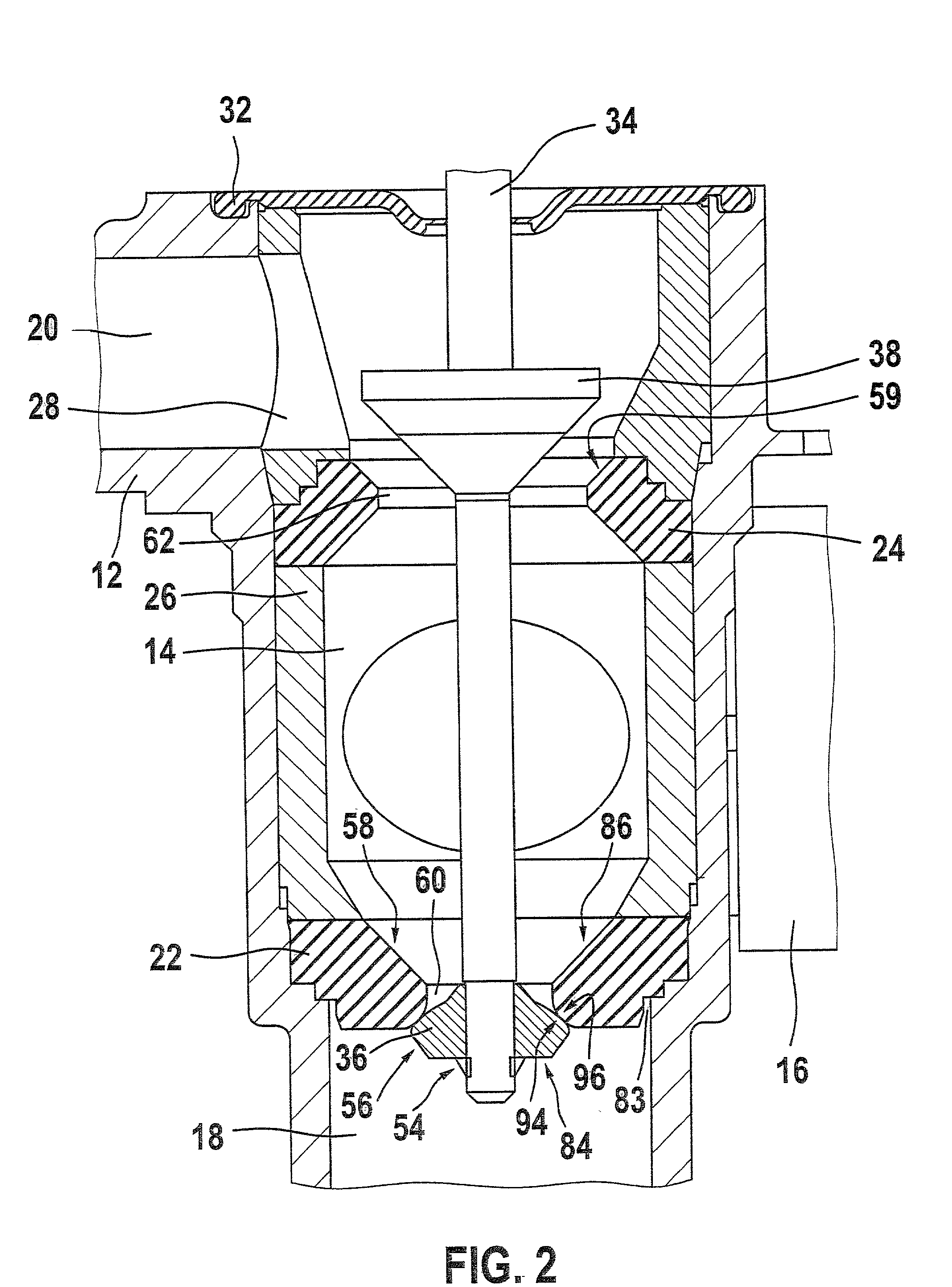
[0020] The valve 10 according to the invention, shown in cross section in FIGS. 1 and 2, has a valve housing 12, which has a valve chamber 14, leading into which are an inlet conduit 16, a first outlet conduit 18, and a second outlet conduit 20. The valve chamber 14 is inserted into the valve housing 12 and is formed by one valve seat 22--at the bottom in FIG. 1 or FIG. 2--facing the first outlet 18; one valve seat 24--at the top in FIG. 1 or FIG. 2--facing toward the second outlet conduit 20; and one spacer sleeve 26, disposed between these two sealing elements, which defines the actual volume of the valve chamber 14. The valve chamber 14 of the valve 10 can thus be replaced, and the valve 10 can thus be adapted more easily to special applications. The valve seats 22 and 24 of the valve chamber 14 are of an elastically stretchable material in this exemplary embodiment, such as NBR (nitrile butadiene rubber) and each have a respective valve opening 60 and 62. The valve chamber 14 is...


PUM


Abstract

The invention relates to a valve (10, 110) having a valve chamber (14, 114), having at least one inlet conduit (16, 116) and one outlet conduit (18, 118), furthermore having a movable lifting rod (34, 134), one end of which opens into an actuator (53), and having at least one valve member (36, 136, 236) secured to the lifting rod (34, 134), and having at least one valve seat (22, 122) cooperating with the valve member (36, 136, 236). It is proposed that the valve seat (22, 122) and/or valve member (36, 136, 236) is elastically deformable in such a way that the elasticity of the valve seat (22, 122) and/or valve member (36, 136, 236) is at least so great that the valve member (36, 136, 236) can be thrust through the valve seat (22, 122) by an in particular external exertion of force and that the valve seat (36, 136, 236) and the valve member (22, 122) return to their outset state.

Description

PRIOR ART[0001] The invention is based on a valve as generically defined by the preamble to the independent claim.[0002] Such valves are known, for instance from German Patent Disclosure DE 197 53 575 A1. The valve described in DE 197 53 575 A1 is a magnetic bypass valve for a liquid-regulated heating or cooling system. Two valve members secured to a lifting rod of the valve regulate the flow between an inlet conduit and two outlet conduits, and one of these outlet conduits takes on the function of a bypass conduit in the heating and cooling cycle. A disadvantage of the valve described in DE 197 53 575 A1 and of all comparable valves is--for reasons of construction--the quite complex assembly of the individual components of the valve. First the sealing rings, which form the valve seats of the valve chamber, and a spacer sleeve that defines the actual valve chamber of the valve have to be thrust onto the lifting rod of the valve. After that, a first valve member, the bypass valve mem...

Claims


Application Information

Patent Timeline
IPC IPC(8): F16K1/44F16K11/048F16K31/06
CPCF16K1/44F16K11/048F16K31/0634Y10T137/6065Y10T137/86895Y10T137/86726Y10T137/6007
Inventor HESS, JUERGENREEB, GEORG
Owner ROBERT BOSCH GMBH
Why Eureka
Try Eureka