Hydraulic tension stop for vibration dampers

a technology of vibration dampers and tension stops, which is applied in the direction of vibration dampers, springs/dampers, springs, etc., can solve the problems of high production costs of components, particle rubbing, and impairing the function of damping devices

Inactive Publication Date: 2002-08-08
ZF SACHS AG
View PDF0 Cites 22 Cited by
  • Summary
  • Abstract
  • Description
  • Claims
  • Application Information

AI Technical Summary

Problems solved by technology

In addition, as a result of the continuous contact between the damping ring and the contact surface, there is also the danger that particles can be rubbed off, which can impair the function of the damping devices.
To ensure that the tension damping functions satisfactorily even under the effect of transverse forces acting on

Method used


Image

  • Hydraulic tension stop for vibration dampers
  • Hydraulic tension stop for vibration dampers
  • Hydraulic tension stop for vibration dampers

Examples


Embodiment Construction

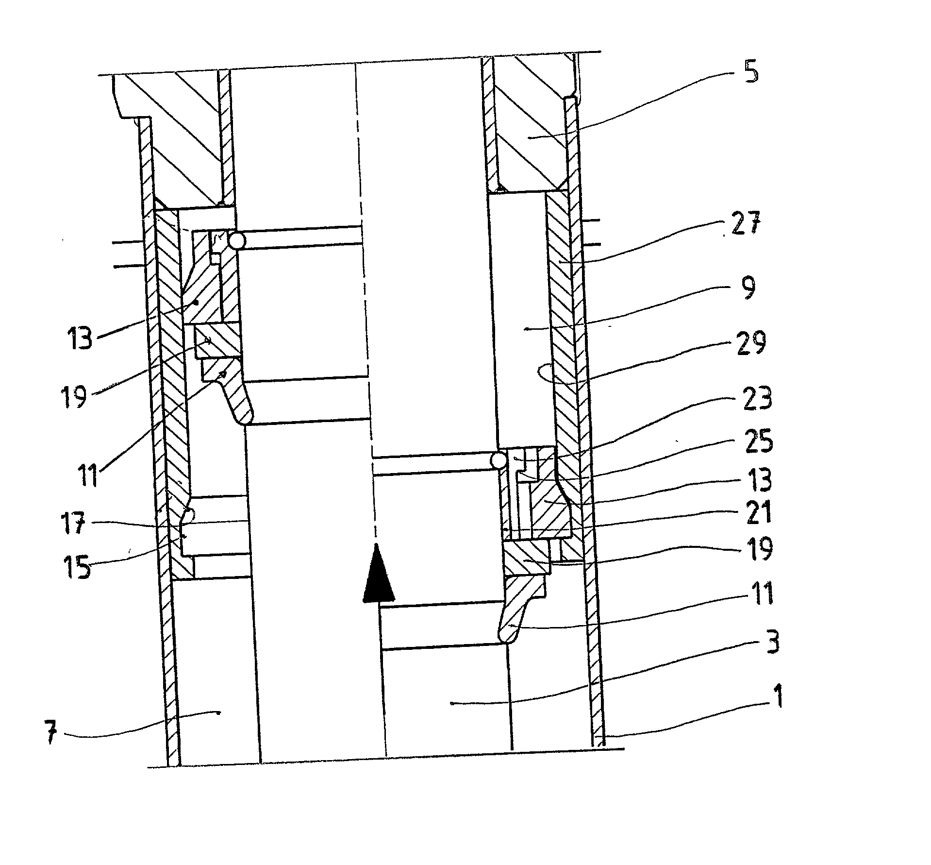
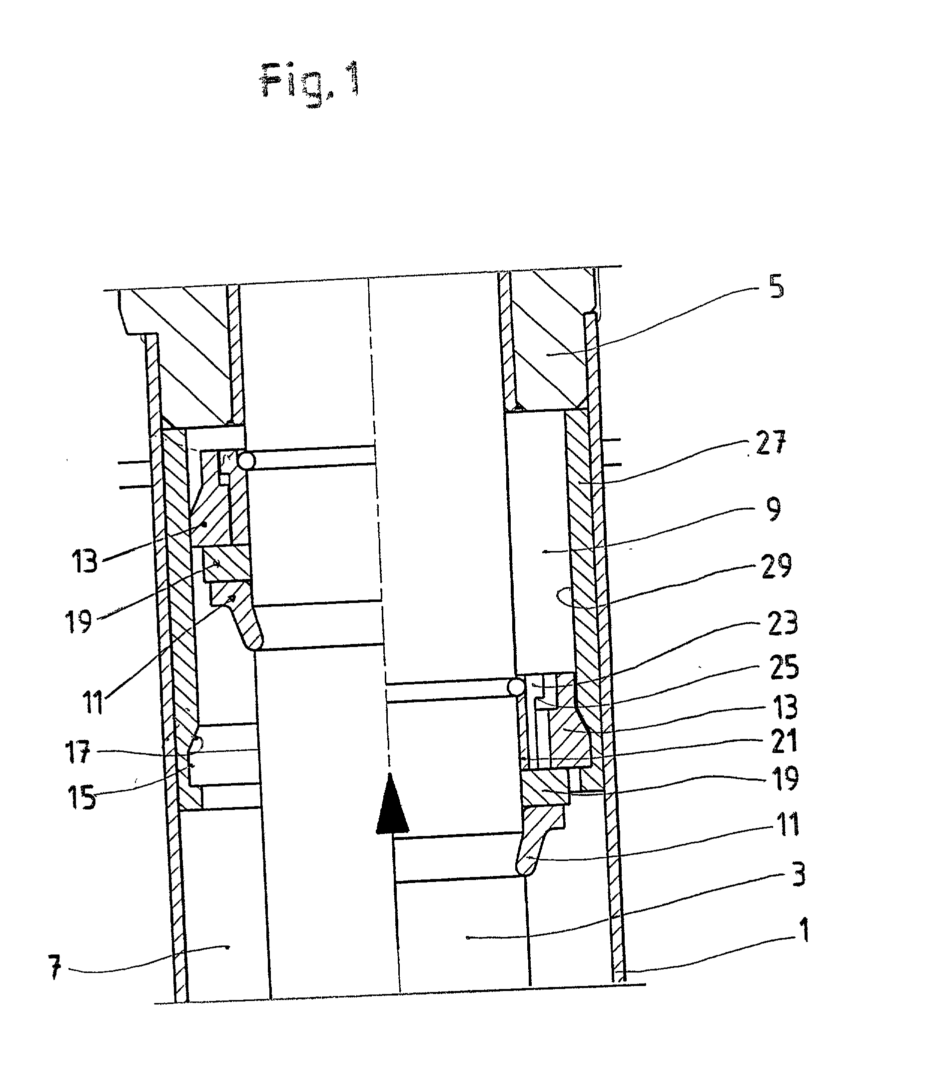
[0022] Because the design and function of standard commercial piston-cylinder assemblies are sufficiently well known to the expert in the field, only the components of these assemblies in the area of the tension stop are shown. It is assumed that the vibration damper is serving as an assembly for a motor vehicle, which assembly is provided with a hydraulic tension stop according to the invention as illustrated by the embodiments shown in the figures. Accordingly, the following description pertains essentially to the design and function of the embodiments of hydraulic tension stops according to the invention.

[0023] The portion of a vibration damper shown in FIG. 1 includes a cylinder 1, in which a piston rod 3, which is free to move in the axial direction and which is sealed off toward the outside, travels back and forth through a piston rod guide 5. A damping piston (not shown), connected to the piston rod 3, is provided with damping devices and operates in the damping fluid-filled ...


PUM


Abstract

Hydraulic tension stop for vibration dampers, shock absorbers, or similar piston-cylinder assemblies, where each assembly has a fluid-filled working space, the boundaries of which are formed axially by a piston rod guide and the piston and radially by the cylinder and the piston rod which carries the piston, part of this working space also belonging to the tension stop. A stop ring is mounted on the piston rod, which ring cooperates with a slotted, outwardly tensioned damping ring, so that the tension damping can be varied as a function of the stroke. When the stop ring reaches a predetermined position, the damping ring seats in a rest-position channel in a slide face permanently attached to the cylinder, the channel having a conical surface.

Description

[0001] 1. Field of the Invention[0002] The invention pertains to a hydraulic tension stop for vibration dampers, shock absorbers, or similar piston-cylinder assemblies of the type including a cylinder, a piston rod carrying a piston, and a piston rod guide. A liquid-filled working space is bounded axially by the piston rod guide and the piston, and radially by the cylinder and the piston rod, a part of the working space being assigned to the tension stop.[0003] 2. Description of the Related Art[0004] A hydraulic tension stop for vibration dampers of this type is known from U.S. Pat. No. 4,901,928. For this purpose, an outwardly tensioned slotted damping ring is arranged with freedom of radial movement in a ring-shaped channel of a piston-like stop body. By way of a shallow conical section, which adjoins the cylindrical contact surface in the axial direction and extends with a taper toward the piston rod guide, the damping ring cooperates with pass-through openings, which lead across...

Claims


Application Information

Patent Timeline
IPC IPC(8): F16F9/49
CPCF16F9/49
Inventor OBST, STEFFEN
Owner ZF SACHS AG
Why Eureka
Try Eureka