
Well drilling method and system

a well and well technology, applied in the direction of drilling pipes, borehole/well accessories, survey, etc., can solve the problems of substantial "uncontaminated" drilling fluid recirculation, well bore at deeper depths may not tolerate significant hydrostatic pressure changes, and drilling fluid circulation may be partially or completely lost to the formation, etc., to facilitate the maintenance of ecd

Inactive Publication Date: 2002-08-15
VAREO SHAFFER
View PDF0 Cites 62 Cited by
  • Summary
  • Abstract
  • Description
  • Claims
  • Application Information

AI Technical Summary

Benefits of technology

[0013] This invention provides methods and systems for drilling a well bore through a subterranean formation whereby the hydrostatic pressure exerted upon the formation by the drilling fluid ("mud") may be maintained substantially the same regardless of whether the drilling fluid is or is not being circulated. The bottom hole pressure exerted on a formation during periods of drilling fluid circulation may be the equivalent circulating density ("ECD"). The ECD may be at least partially dependent upon circulation rate and fluid density. The methods and systems of this invention may facilitate maintaining the ECD when circulation is interrupted, such as when a joint of drill pipe is added to or removed from the drill string.

Problems solved by technology

When the circulated drilling fluid arrives back at the surface, cuttings and other solid contaminants are commonly separated from the circulated drilling fluid such that substantially "uncontaminated" drilling fluid may be recirculated.
Traditional overbalanced drilling techniques practice maintaining a hydrostatic pressure on the formation equal to or slightly overbalanced with respect to formation pore pressure.
Certain formations penetrated by the well bore at deeper depths may not tolerate significant changes in hydrostatic pressure.
Hydrostatic pressure changes may result in either a formation fluid influx into the wellbore (a "kick") or in the drilling fluid invading or being lost into the formation ("lost circulation").
Care may be required during startup and during circulation to avoid the ECD exceeding either or both the pore pressure in the formation and the fracture pressure of the formation matrix, which may result in drilling fluid circulation being partially or completely lost to the formation.
Loss of circulation may result in loss of well control, loss of expensive drilling fluids, stuck drill pipe, or other related adverse consequences.
Thereby, the startup ECD and the circulating ECD are both disadvantages of prior art.
The changes in circulation pressure and the corresponding changing hydrostatic pressure exerted upon the formation results in reduced control of hydrostatic pressure exerted upon the formation.
Those skilled in the industry may appreciate that increased drilling fluid density and hydrostatic pressure may result in reductions in rate of penetration ("ROP") by the drill bit, further resulting in increase time and well costs.
The hydrostatic pressure fluctuations, the complex determinations of actual circulating bottom hole pressure, the increased fluid density, and the resultant decreased ROP are also disadvantages of the prior art.

Method used


Image

  • Well drilling method and system
  • Well drilling method and system

Examples


Embodiment Construction

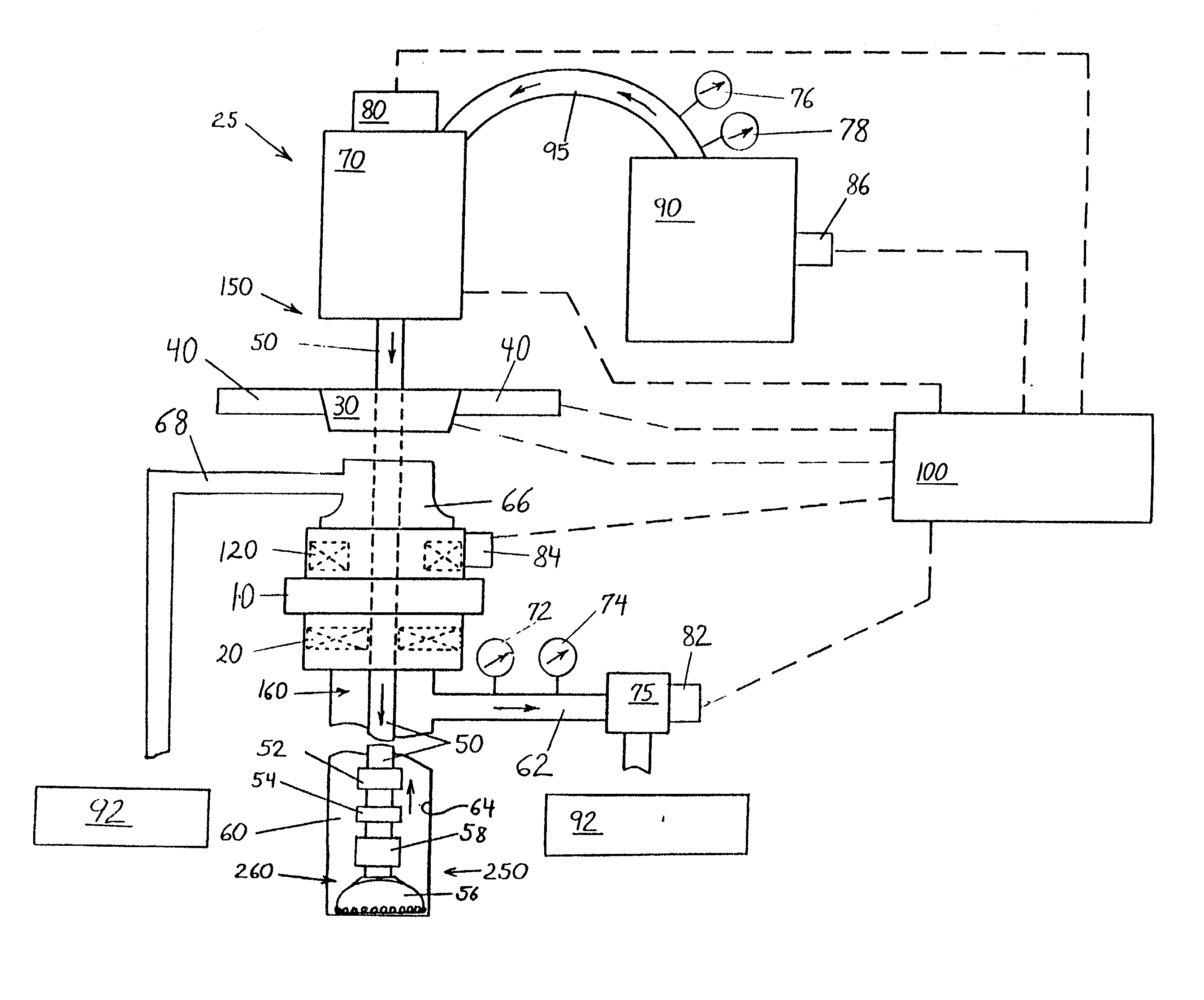
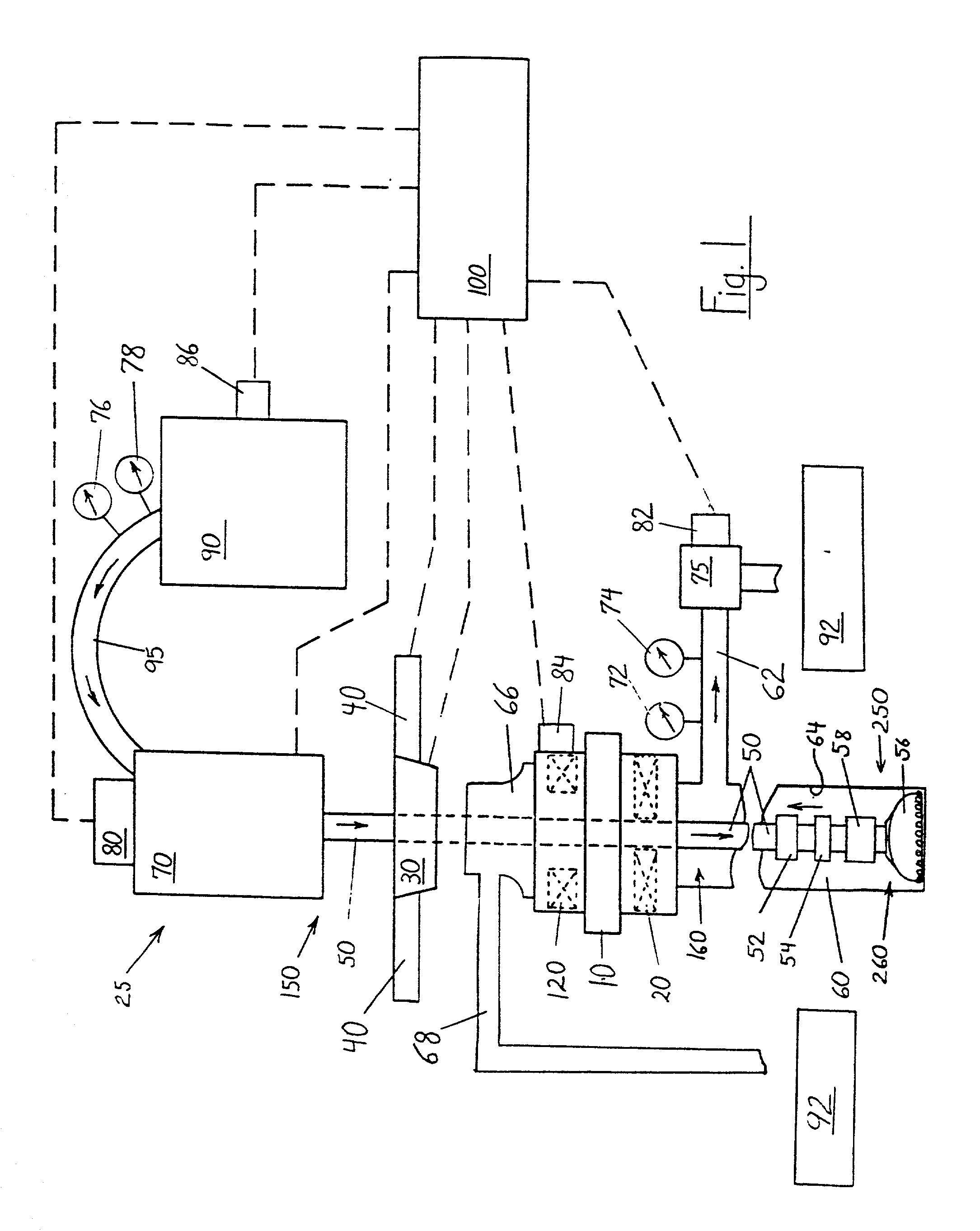
[0031] FIG. 1 illustrates an arrangement for components which may be included with a drilling rig 25 and which may be utilized to practice the present invention. A preferred embodiment for a system and method for drilling a well bore 60 through a subterranean formation may include a drill bit 56 supported upon a lower end of a drill string 250. The lower end of the drill string 250 may extend into a well bore 60. An upper end of the drill string 150 may be located at a drilling rig 25 at the surface. The drill string 50 may include a through bore to conduct a drilling fluid ("mud") through the drill string 50. The drill string 50 may comprise a series of interconnected joints of drill pipe.

[0032] A mud pump 90 located near the drilling rig 25 may pump a drilling fluid through a mud line 95, then into the upper end of the drill string 150, then through the drill string 50, then through the drill bit 56. The drill bit 56 may be located near a lower end of the well bore 260. The drilli...


PUM


Abstract

Methods and systems are provided for drilling a well bore 60 through a subterranean formation using a drilling rig 25 and a drill string 50, whereby the bottom hole pressure while circulating drilling fluid ("ECD") may be substantially maintained when circulation is interrupted or altered, such as when adding a joint of drill pipe to or removing a joint of drill pipe from the drill string. The method includes controllably applying and maintaining a desired variable annulus fluid pressure in the well bore, and thereafter controllably releasing the pressure from the well bore 60. In addition, methods and systems are provided for rotating the drill string while trapping, maintaining and / or releasing the well bore pressure. A substantially constant ECD pressure may be maintained on a formation, thereby facilitating the use of a lower density drilling fluid than may otherwise be required to maintain well control. In one embodiment, a drill pipe connection may be made up and / or broke out while the drill string continues to rotate.

Description

RELATED APPLICATION[0001] This application is a continuation of U.S. Ser. No. 09 / 668,440 filed Sep. 22, 2000, now U.S. Pat. No. 6,374,925.FIELD OF THE INVENTION[0002] The present invention relates to drilling subterranean well bores of the type commonly used oil or gas wells. More particularly, this invention relates to an improved method and system for maintaining bottom hole hydrostatic pressure while making a drill pipe connection. The methods and system of this invention facilitate improving hydrostatic control of a well bore while drilling with a reduced equivalent circulating density ("ECD").BACKGROUND OF THE INVENTION[0003] Drilling subterranean wells typically requires circulating a drilling fluid ("mud") through a drilling fluid circulation system ("system"). The circulation system may include a drilling rig located substantially at the surface. The drilling fluid may be pumped by a mud pump through the interior of a drill string, through a drill bit and back to the surface...

Claims


Application Information

Patent Timeline
Patent Type & Authority Applications(United States)
IPC IPC(8): E21B19/16E21B21/08
CPCE21B19/16E21B21/08
Inventor ELKINS, HUBERT L.MERIT, MARK A.
Owner VAREO SHAFFER
Learn More