Device and method to mitigate hydrogen explosions in vacuum furnaces

a vacuum furnace and hydrogen explosion technology, applied in the direction of furnaces, lighting and heating equipment, crucible furnaces, etc., can solve the problem that the pressure relief device occasionally remains stuck, and achieve the effect of reducing the risk of explosion

Inactive Publication Date: 2002-08-29
STAMPS DOUGLAS WAYNE
View PDF2 Cites 10 Cited by
  • Summary
  • Abstract
  • Description
  • Claims
  • Application Information

AI Technical Summary

Problems solved by technology

However, pressure relief devices occasionally remain stuck open.

Method used


Image

  • Device and method to mitigate hydrogen explosions in vacuum furnaces
  • Device and method to mitigate hydrogen explosions in vacuum furnaces
  • Device and method to mitigate hydrogen explosions in vacuum furnaces

Examples


Embodiment Construction

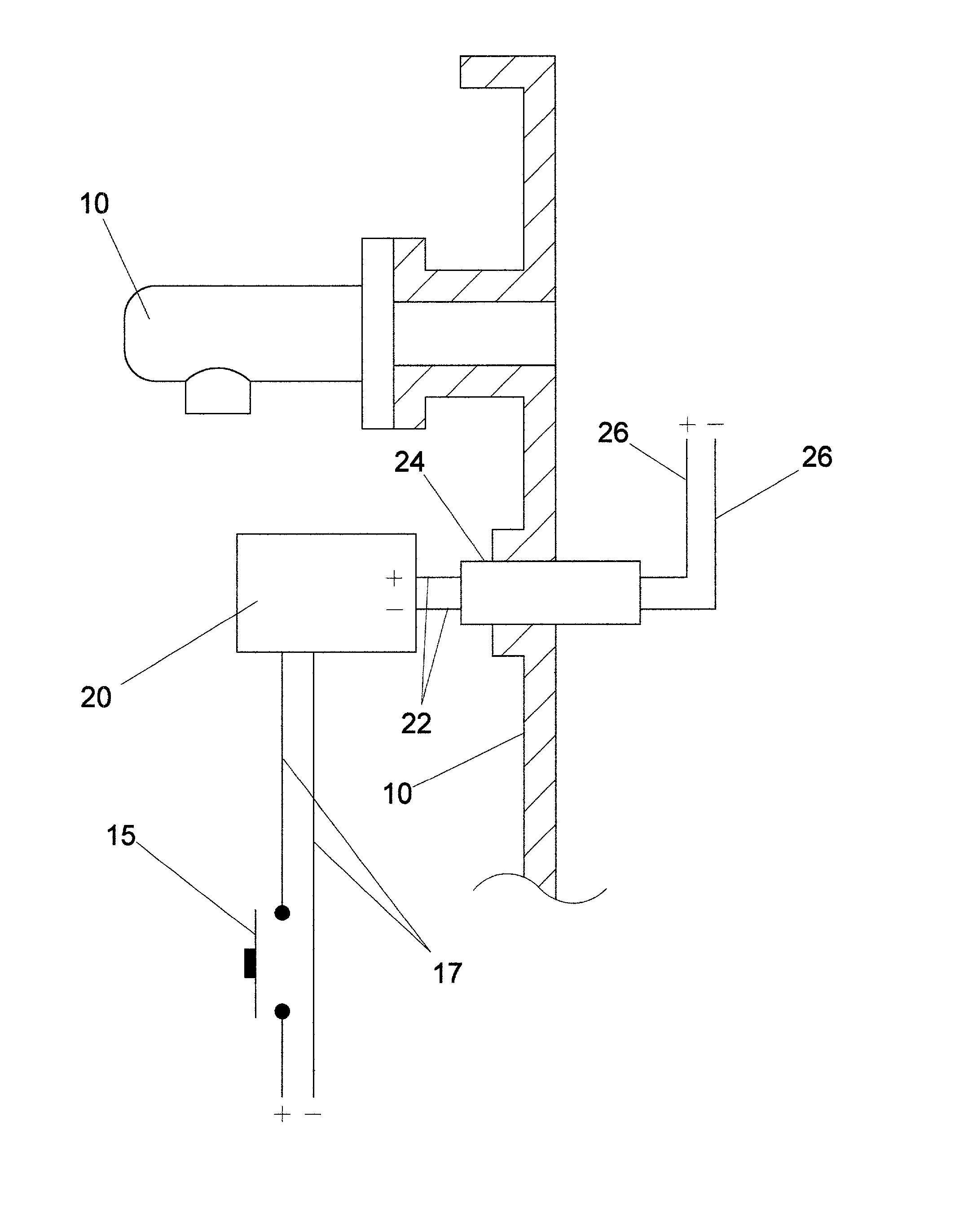
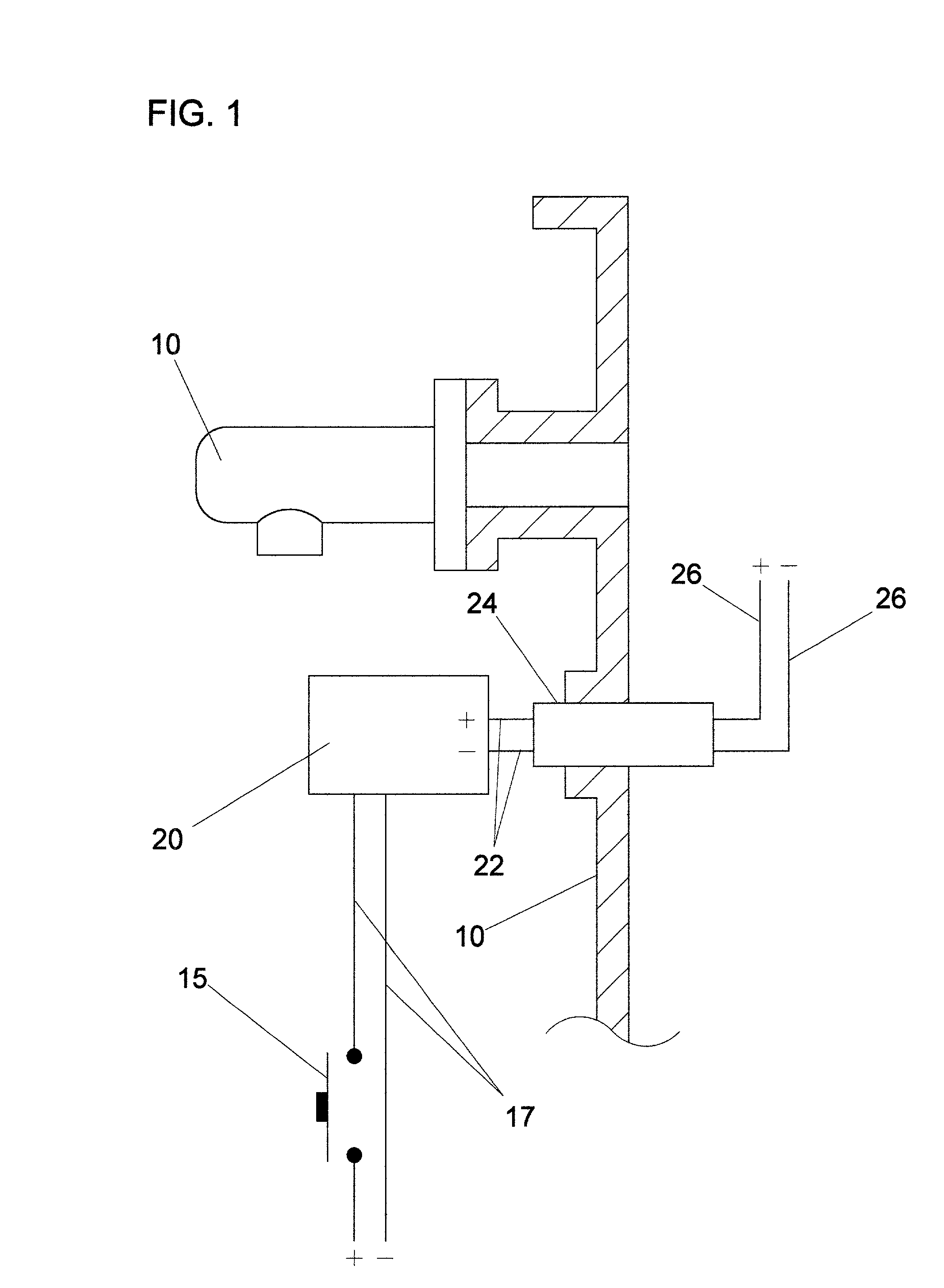
[0025] A typical embodiment of the device of the present invention is illustrated in FIG. 1. A set of electrodes 26 is located inside a melt chamber tank 28. The set of electrodes 26 is positioned near a location where air can enter the melt chamber tank 28, including a pressure relief device 10. A pair of high-voltage wires 22 is connected to the electrodes 26. The pair of high- voltage wires 22 have a positive and negative electrical line. The pair of high-voltage wires 22 pass through the wall of the melt chamber tank 28 by a vacuum-tight feedthrough 24. An ignition transformer 20 on the outside of the melt chamber tank 28 is connected to the pair of high-voltage wires 22. Power is supplied to the ignition transformer 20 through a pair of electrical wires 17 having a positive and negative potential. An electrical switch 15 is connected to the positive line of the pair of electrical wires 17.

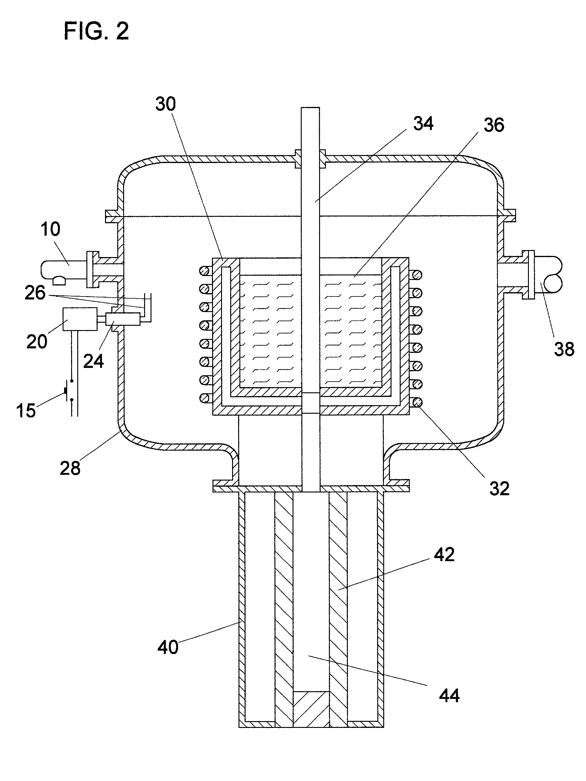
[0026] FIG. 2 shows a typical vacuum-melting furnace with induction heating and bottom pou...


PUM


Abstract

A device to mitigate hydrogen explosions in a vacuum furnace includes at least one igniter, an ignition transformer, and an electrical switch. The at least one igniter includes a set of high-voltage electrodes and is connected to the ignition transformer by high-voltage wires. The electrical switch activates the ignition transformer to provide power to the at least one igniter forming a continuous electrical arc between the electrodes. The at least one igniter is located inside the vacuum furnace at an opening where air may enter the vacuum furnace, which may contain a hydrogen and steam gas mixture under accident conditions. The device consumes hydrogen by controlled combustion as flammable mixtures are formed.

Description

[0001] 1. Field of Invention[0002] This invention relates to a method and device for controlled combustion of accidentally formed explosive mixtures contained within vacuum furnaces, in particular vacuum induction-melt furnaces and vacuum arc-melt furnaces, having at least one igniter and at least one ignition source.[0003] 2. Description of Prior Art[0004] It has been a long-standing problem that explosions occur in the processing and casting of reactive metals, such as titanium and zirconium. For example, since the commercial development of the titanium processing industry in the early 1950's, there has been a continual problem of explosions with catastrophic loss of human life and / or capital equipment.[0005] The explosions form under accident conditions. The accident begins when water comes in contact with the molten reactive metal. In the case of the vacuum arc-melting furnaces, one mode of failure occurs when the tip of a water-cooled non-consumable electrode blows off and high...

Claims


Application Information

Patent Timeline
Patent Type & Authority Applications(United States)
IPC IPC(8): F23N1/02F23N5/20F23N5/24F27B14/04F27B14/06F27D21/00
CPCF23N1/02F23N5/20F23N5/24F23N2027/36F27B14/063F27B2014/045F27D2021/0071F23N2227/36
Inventor STAMPS, DOUGLAS WAYNE
Owner STAMPS DOUGLAS WAYNE
Why Eureka
Try Eureka