Magnetic disk unit

Inactive Publication Date: 2002-08-29
HITACHI GLOBAL STORAGE TECH JAPAN LTD
View PDF0 Cites 15 Cited by
  • Summary
  • Abstract
  • Description
  • Claims
  • Application Information

AI Technical Summary

Benefits of technology

0006] The object of the invention is to obtain a magnetic disk unit having a plurality of suspensions in the same cylinder, in which magnetic disk unit, even at a time when reading/writing operation is transferred from the first suspension to the s

Problems solved by technology

Since the flow rate of air flow above the inner periphery of the disk differs from that above the outer periphery thereof, the temperature of the IC varies in a case of heating with

Method used


Image

  • Magnetic disk unit
  • Magnetic disk unit
  • Magnetic disk unit

Examples


Embodiment Construction

[0023] The embodiments of the invention are described in detail below while referring to the drawings.

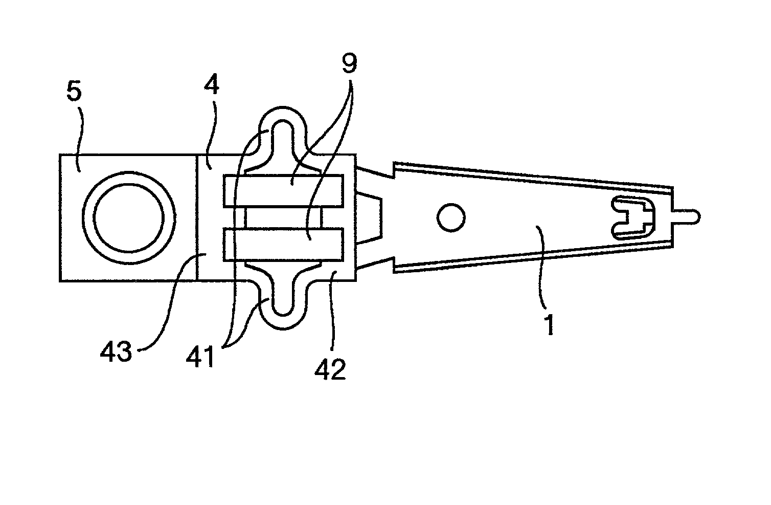
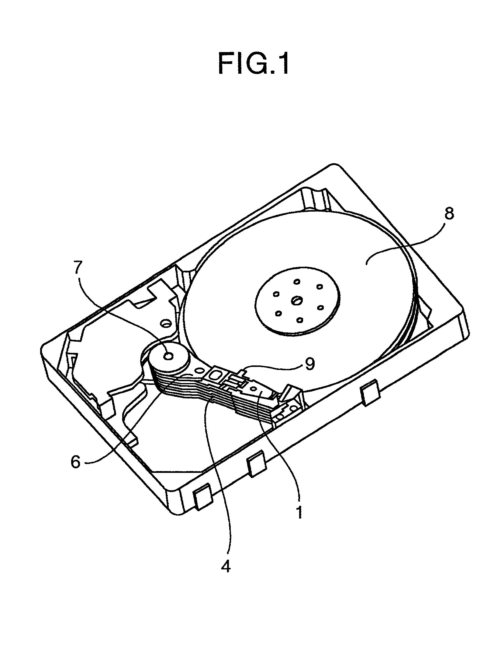
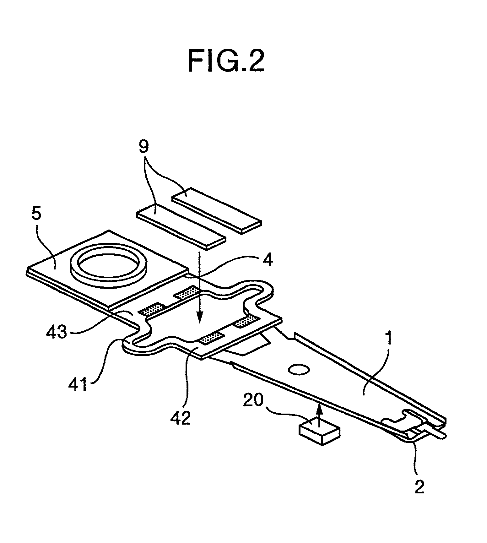
[0024] FIG. 1 is a perspective view of a magnetic disk unit embodying the invention, FIG. 2 being a perspective view of a suspension used therein, FIG. 3 being a side view of the suspension, and FIG. 4 is a top view of the suspension.

[0025] As shown in FIGS. 1 to 4, a slider 3 is attached to the end portion of a load beam 1 through a flexure 2, a magnetic head 22 being mounted on the slider 3. At the side of the slider 3 attached to the load beam 1 is mounted an IC 20 for amplifying the reading / writing signals of the magnetic head 22 (which IC is below referred to as "IC for the magnetic head"). In the IC for the magnetic head are provided temperature-detecting means (sensor). The temperature-detecting means comprise a sensor detecting a temperature by use of variation of the resistance value of a semiconductor diode which variation occurs during the temperature variation of the sem...


PUM


Abstract

In the magnetic disk unit comprising suspensions in each of which an IC is mounted on a load beam, a magnetic head displacement caused by the warp of the load beam occurring due to heat generated from the IC is compensated, whereby the shortening of an access speed and high reliability of reading/writing are realized. The thermal displacement of the magnetic head is compensated by operating micro actuators on the load beam in accordance with the temperature rise of the IC which is measured by a temperature sensor. Namely, by driving the micro actuators so that the magnetic head may move in a direction reverse to the direction of the magnetic head movement caused by the thermal displacement, the thermal displacement of the magnetic head is made to be substantially zero.

Description

[0001] The invention relates to a magnetic disk unit, and particularly relates to a magnetic disk unit having two types of actuators, that is, coarse actuators for large movement and micro actuators and further having a controlling IC on a suspension supporting a magnetic head.[0002] As a prior art of the invention, JP-A-11-195215 discloses that, in a magnetic head-supporting mechanism having two-stage actuators and an IC (integrated circuit) mounted in a suspension, the mechanism is provided with means for preventing the IC itself from being damaged due to heat occurring during the operation of the IC. Further, regarding a conventional head-supporting mechanism of one stage, JP-A-4-103085 discloses a controlling method for compensating the position deviation of the head-supporting mechanism which deviation occurs due to temperature rise of a magnetic disk unit.[0003] In a chip-on-suspension (hereinafter referred to as COS) in which an IC is mounted on a suspension, there is such a ...

Claims


Application Information

Patent Timeline
IPC IPC(8): G11B5/48
CPCG11B5/486
Inventor TOKUYAMA, MIKIOSHIMIZU, TOSHIHIKOMASUDA, HIROMITSUNAKAMURA, SHIGEO
Owner HITACHI GLOBAL STORAGE TECH JAPAN LTD
Why Eureka
Try Eureka