Image processing system, image forming system, and recording medium

Inactive Publication Date: 2002-09-05
FUJIFILM BUSINESS INNOVATION CORP
View PDF2 Cites 14 Cited by
  • Summary
  • Abstract
  • Description
  • Claims
  • Application Information

AI Technical Summary

Problems solved by technology

Therefore, when a light thin line is to be drawn, the interference between the thin line and the drawing pattern occurs.
In particular, in the light thin line having the angle that is close to the screen angle, there is the problem that the thin line is not drawn in many infinitesimal areas that successively appear in the extending direction of the thin line and that the lig

Method used


Image

  • Image processing system, image forming system, and recording medium
  • Image processing system, image forming system, and recording medium
  • Image processing system, image forming system, and recording medium

Examples


Example

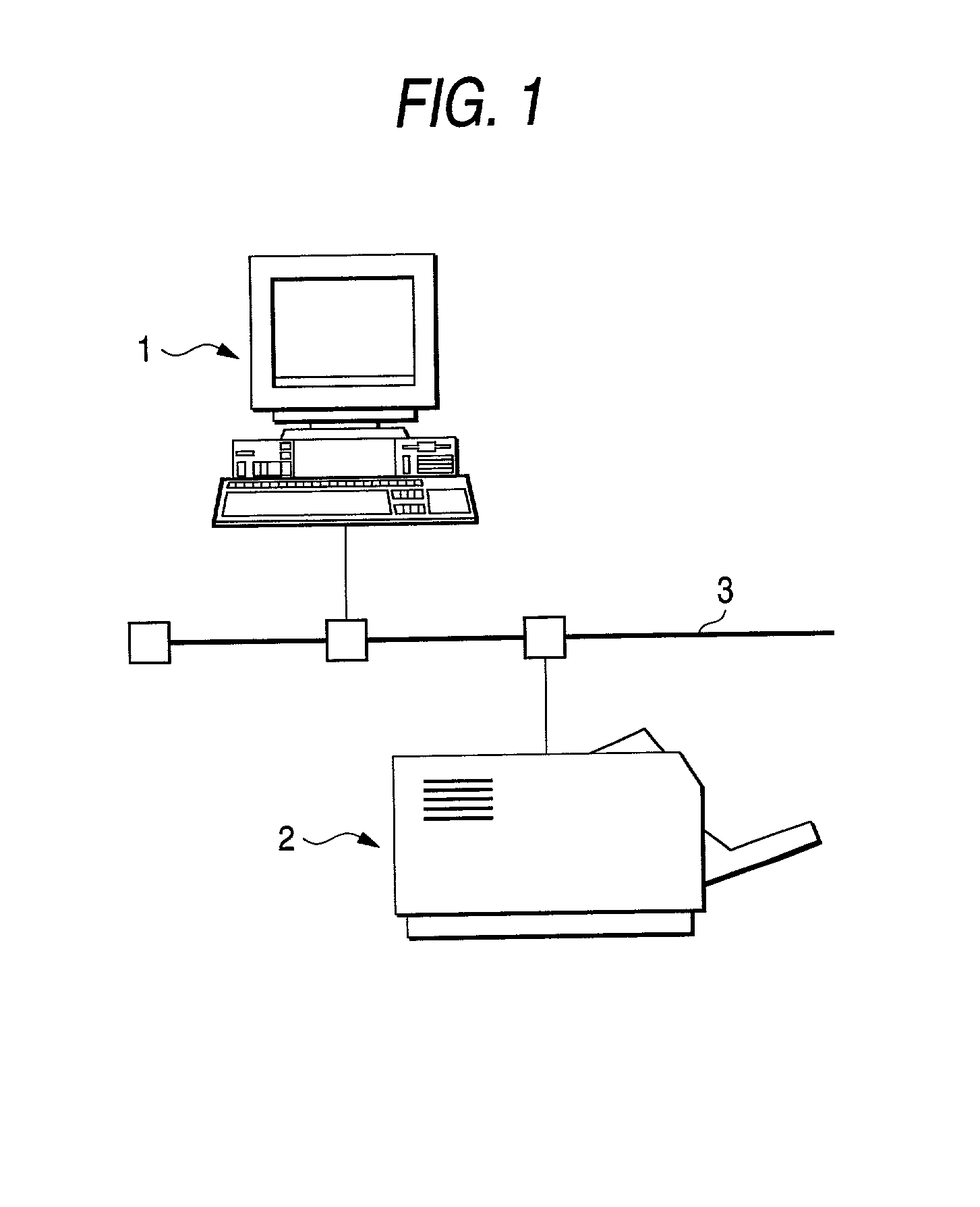
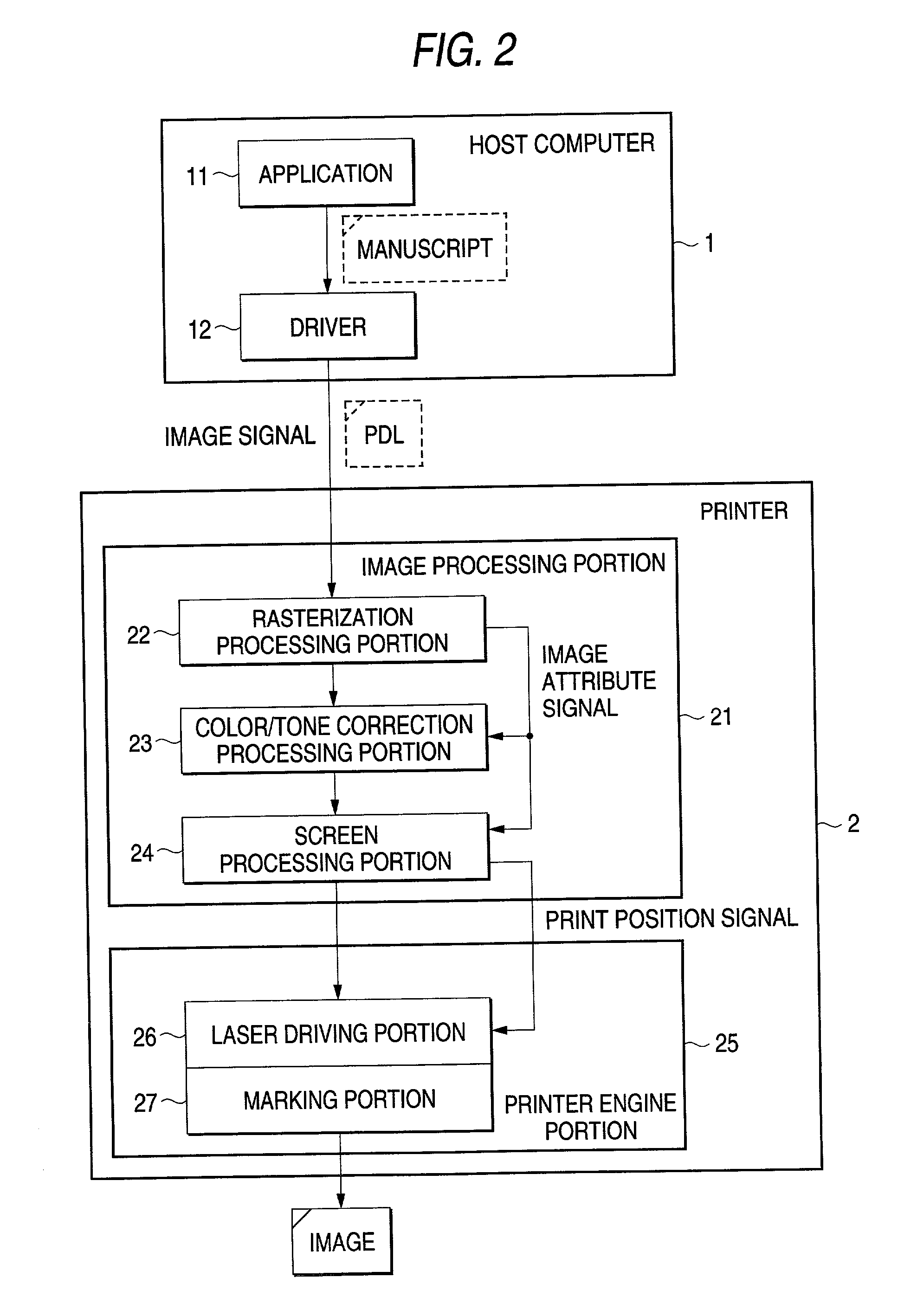
[0041] FIG.1 is a schematic view showing an example of a configuration of image forming systems containing an embodiment of an image forming system of the present invention. FIG. 2 is a block diagram showing an example of the image forming systems containing the embodiment of the image forming system of the present invention. In FIG.1 and FIG.2, 1 is a host computer, 2 is a printer, 3 is a network, 11 is an application, 12 is a driver, 21 is an image processing portion, 22 is a rasterization processing portion, 23 is a color / tone correction processing portion, 24 is a screen processing portion, 25 is a printer engine portion, 26 is a laser driving portion, and 27 is a marking portion. In this example, the image forming system of the present invention shows an example containing the image processing system of the present invention.

[0042] The image forming system shown in FIG.1 comprises the host computer 1 and the printer 2, and both are connected via the network 3. Also, there is th...


PUM


Abstract

A maximum color identifying portion 41 identifies a maximum color from coloring material colors used to reproduce a color of a line segment after color conversion into coloring material colors by a character/line color converting portion 31 is applied to the rasterized image signal. A structure deciding portion 42 outputs a screen parameter flag that controls a screen parameter in compliance with the identified maximum color and a drawing direction of the line segment such that the screen process in the maximum color is executed at a screen angle, that is different from the drawing direction of the line segment, in a character/line screen processing portion 35. The character/line screen processing portion 35 applies the screen process to the image in accordance with the screen parameter flag by using the screen parameter at the screen angle that is different from the drawing direction of the line segment. Accordingly, disappearance of the line segment due to the screen process is avoided.

Description

[0001] 1. Technical Field[0002] The present invention relates to an image processing system and an image forming system for applying a screen process to an input image, and a recording medium for storing a program that causes a computer to execute such process.[0003] 2. Related Art[0004] In the color image forming system, the color reproduction in full color can be achieved by using a plurality of coloring materials. The color image is formed by superposing the corresponding color image every coloring material. In superposing respective color images, slight displacement is caused due to the precision. The displacement in the superposition causes the generation of the moire, etc. on the image.[0005] In order to prevent the generation of the moire, etc. due to the displacement in the superposition of respective color images, normally the rotation screen in which the screen angle to the image in the screen process is changed every coloring material color is employed. The screen angle i...

Claims


Application Information

Patent Timeline
IPC IPC(8): B41J2/52B41J2/525G06F3/12G06K15/02B41J5/30G06T5/00H04N1/52H04N1/60
CPCG06K15/02G06K2215/0094
Inventor KITAGAWARA, ATSUSHI
Owner FUJIFILM BUSINESS INNOVATION CORP
Why Eureka
Try Eureka