
Self-clocking multiphase power supply controller

a multi-phase power supply and controller technology, applied in the direction of electric variable regulation, process and machine control, instruments, etc., can solve the problems of linear regulation inefficiency rising with increasing input/output voltage differential, unable to provide dramatic performance gains for modern microprocessors, and unable to operate at 2 vdc, so as to increase the noise immunity of ripple-mode regulation and extend the flexibility of the effect of flexibility

Inactive Publication Date: 2002-09-12
SEMTECH CORP
View PDF0 Cites 133 Cited by
  • Summary
  • Abstract
  • Description
  • Claims
  • Application Information

AI Technical Summary

Benefits of technology

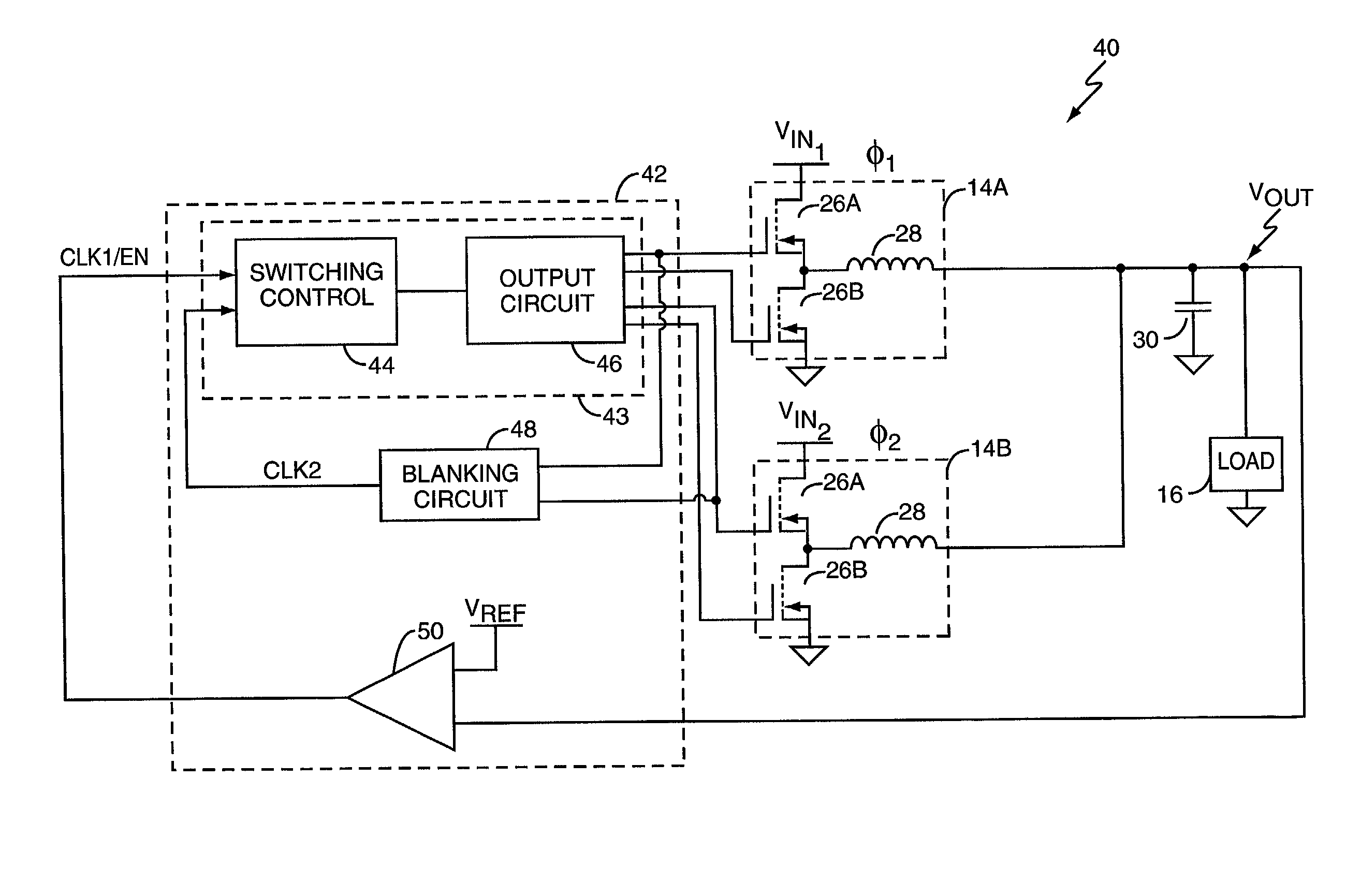
[0008] The present invention provides an apparatus and method for ripple-mode control of a multi-phase power supply circuit. A ripple-mode switching controller provides one or more features, including cross-phase blanking, active current sharing, out-of-bounds compensation, and virtual ripple generation. Cross-phase blanking permits the controller to preserve the desired phase relationship between switching pulses it provides to the multiple output phases, even when it generates overlapping switching pulses at maximum duty cycle operation. Active current sharing compliments ripple-mode control by allowing the controller to balance the amount of load current provided by the individual output phases, based on either trimming the width of switching pulses provided to one or more output phases, or based on trimming hysteretic control points. The controller may also include an out-of-bounds function to suppress switching pulses in over-voltage situations, and virtual ripple generation to enhance ripple-mode noise immunity.

Problems solved by technology

Indeed, modern microprocessors could not provide their dramatic performance gains absent today's sophisticated power supplies.
For example, high-end microprocessors can consume in excess of 80 Watts of power and operate at 2 VDC or less.
Linear voltage regulation, where a pass element such as a transistor, is used to drop a supply voltage down to a regulated value have good transient response, but can be inefficient.
Linear regulation inefficiency rises with increasing input / output voltage differential.
Regulating such voltages down to 2 VDC or less, as is common for high-performance microprocessor cores, is impractical using linear regulation.
However, switch mode power supplies entail a host of potential problems that sometimes offset their good efficiencies.
For example, the transient response of switch mode power supplies can be compromised depending upon the control topology employed.
In certain feedback implementations, relatively slow error amplifiers reside within the control feedback loop, making the switch mode power supply slow to respond to fast load transients.

Method used


Image

  • Self-clocking multiphase power supply controller
  • Self-clocking multiphase power supply controller
  • Self-clocking multiphase power supply controller

Examples


Embodiment Construction

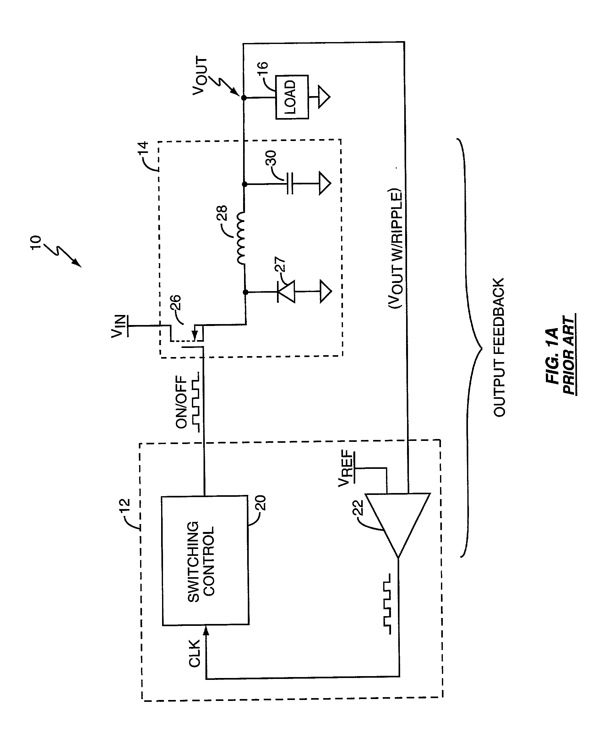
[0025] FIG. 1 illustrates a typical electrical system 10 that includes a switch-mode power supply controller 12, a switching circuit 14, and a load 16. The controller 12 controls switching of the switching circuit 14 to effect voltage regulation of the output voltage V.sub.OUT. The controller includes switching control logic 20 and a comparator 22. The output circuit 14 includes a switch 26, which may be a field-effect-transistor (FET), a catch diode 27, an inductor 28, and an output capacitor 30.

[0026] The controller 12 monitors the output voltage V.sub.OUT using the comparator 22 and generates switching signals that turn the switch 26 on and off to regulate the output voltage V.sub.OUT. The general operation of such switch-mode power supply circuits is well understood, and will not be discussed in detail.

[0027] Several techniques exist for monitoring the output signal being regulated by the controller 12, in this case V.sub.OUT, and include voltage-mode and current-mode feedback. ...


PUM


Abstract

A ripple-mode controller provides reliable operation in multi-phase power supply circuits, over a variety of operating conditions. Cross-phase blanking allows the controller to preserve the desired phase relationship between the switching pulses its provides to the different output phases, and permits the controller to operate each output phase at nearly 100% duty cycles. Active current sharing compliments blanking operations by adjusting the width of switching pulses the controller provides to one or more of the output phases based on detecting load current imbalances between the different output phases. With active current sharing, the controller prevents one or more output phases from carrying excessive portions of the load current. Further complimenting its operation, the controller may include virtual ripple generation to increase the noise immunity of its ripple-mode regulation.

Description

BACKGROUND OF THE INVENTION[0001] The present invention relates to power regulation, and particularly relates to switch-mode power supplies.[0002] Advances in one area of technology often require commensurate advances in supporting technologies to realize the full benefit of the advance. For example, observers of the microprocessor industry are familiar with "Moore's Law," which posits that the complexity of semiconductor devices doubles every two years. Microprocessor development arguably represents the most dramatic illustration of Moore's Law. Pioneering microprocessors released in the 1970's operated at clock speeds well under 500 KHz, and included fewer than five thousand transistors. Modern microprocessors operate at clock speeds in excess of 1 GHz and include millions of transistors. Exploiting these dramatic gains required advances in a host of supporting technologies, from advances in memory technology and circuit fabrication, to advances in power supply design.[0003] Indee...

Claims


Application Information

Patent Timeline
IPC IPC(8): H02M3/158
CPCH02M3/1584H02M3/1588H02M2003/1586Y02B70/1466Y02B70/10H02M3/1586
Inventor GROOM, TERRY J.PULLEN, STUARTLIU, KWANG H.
Owner SEMTECH CORP
Learn More