Comparator circuit

Inactive Publication Date: 2002-09-12
SIEMENS AG
View PDF0 Cites 24 Cited by
  • Summary
  • Abstract
  • Description
  • Claims
  • Application Information

AI Technical Summary

Benefits of technology

0007] The invention discloses a comparator circuit allowing to combine l

Problems solved by technology

However, the above positive feedback causes the reference voltage Vref to change stepwise at any zero crossing of the differential input voltage (Vref-Vi), thereby giving rise to an hysteresis response, which is inherent to Schmitt-Trigger type comparator circuits.
However, to

Method used


Image

  • Comparator circuit
  • Comparator circuit
  • Comparator circuit

Examples


Embodiment Construction

[0043] The invention relates to a comparator circuit, and in particular, to a comparator circuit to lower power consumption and increase the accuracy of level detection.

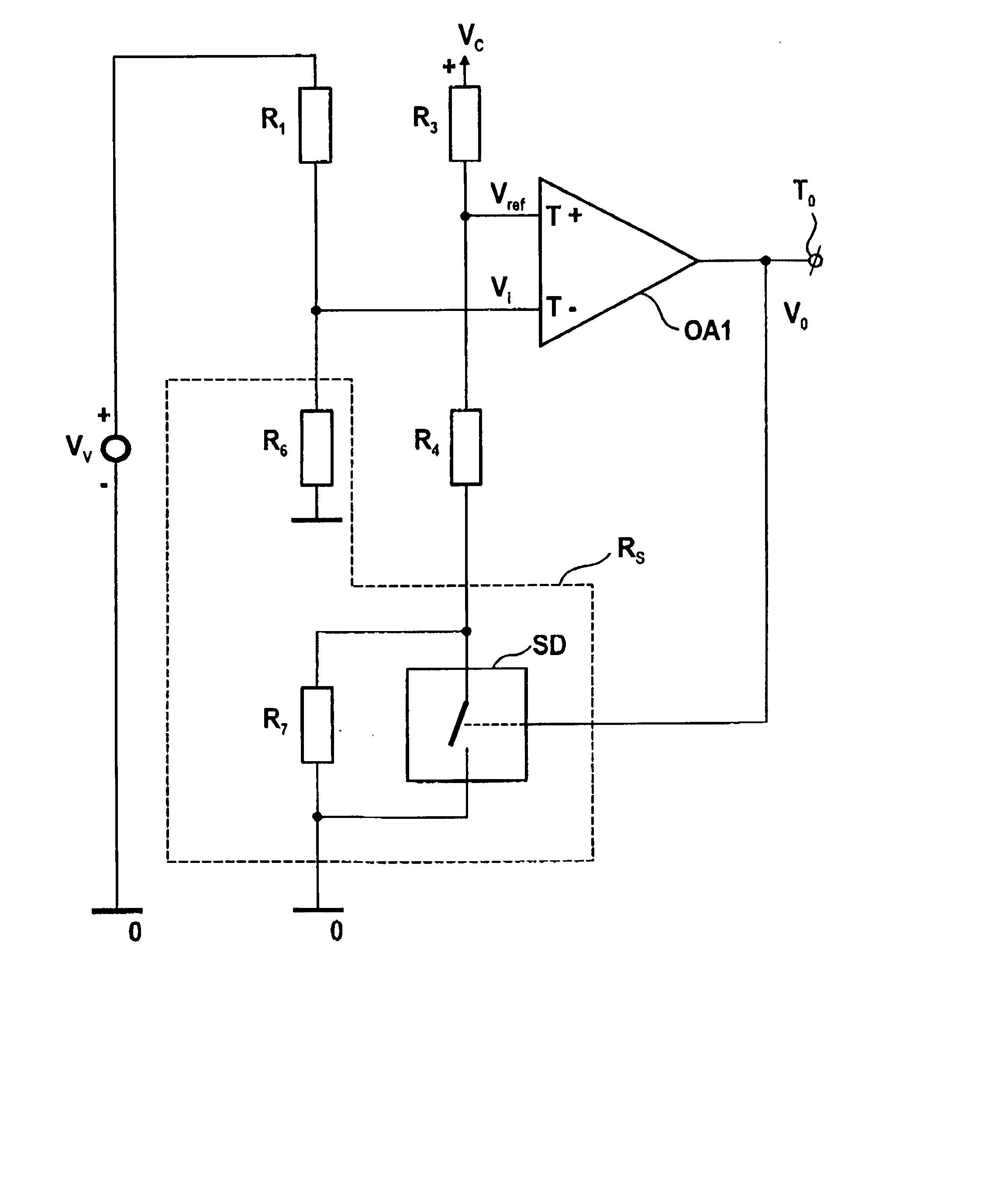
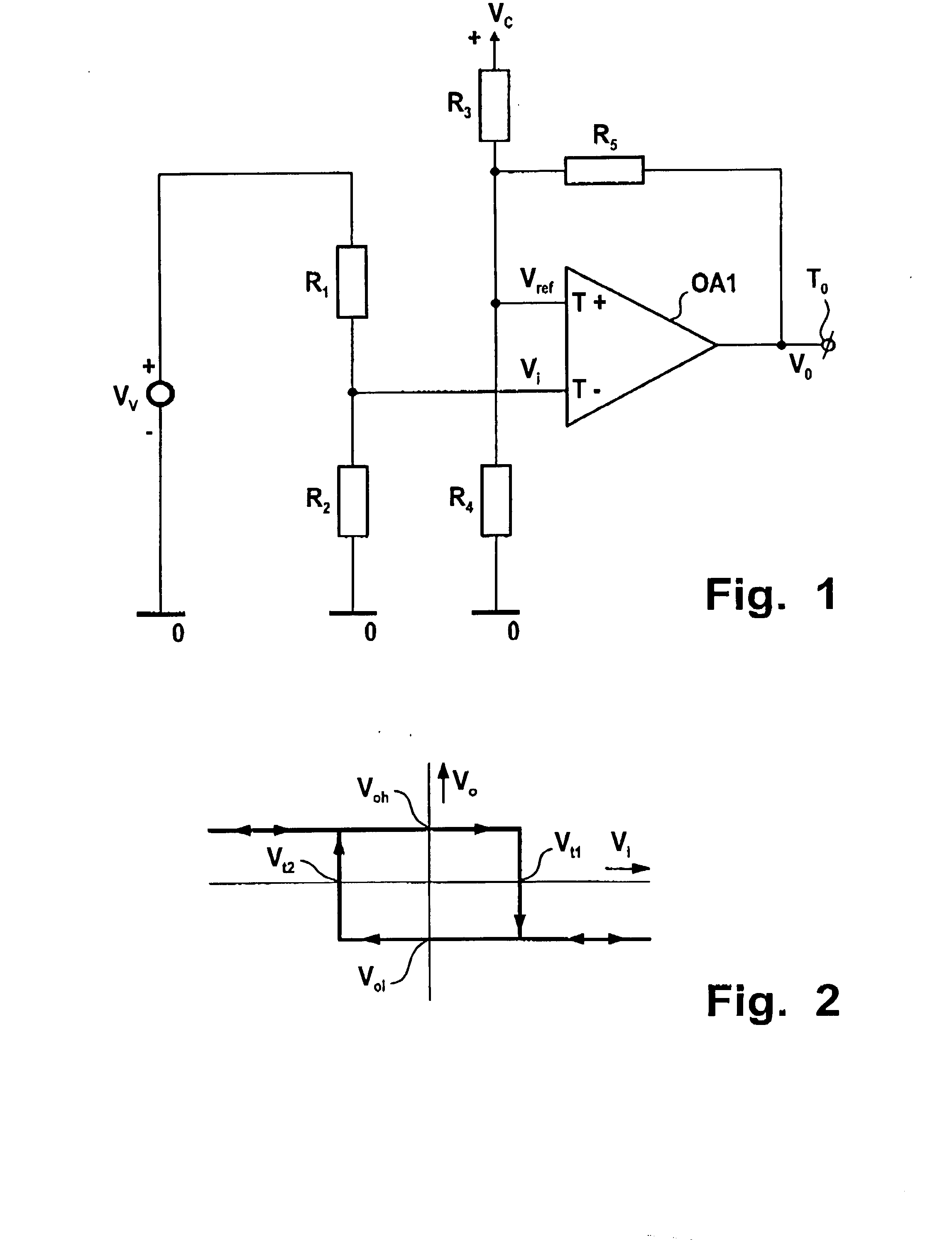
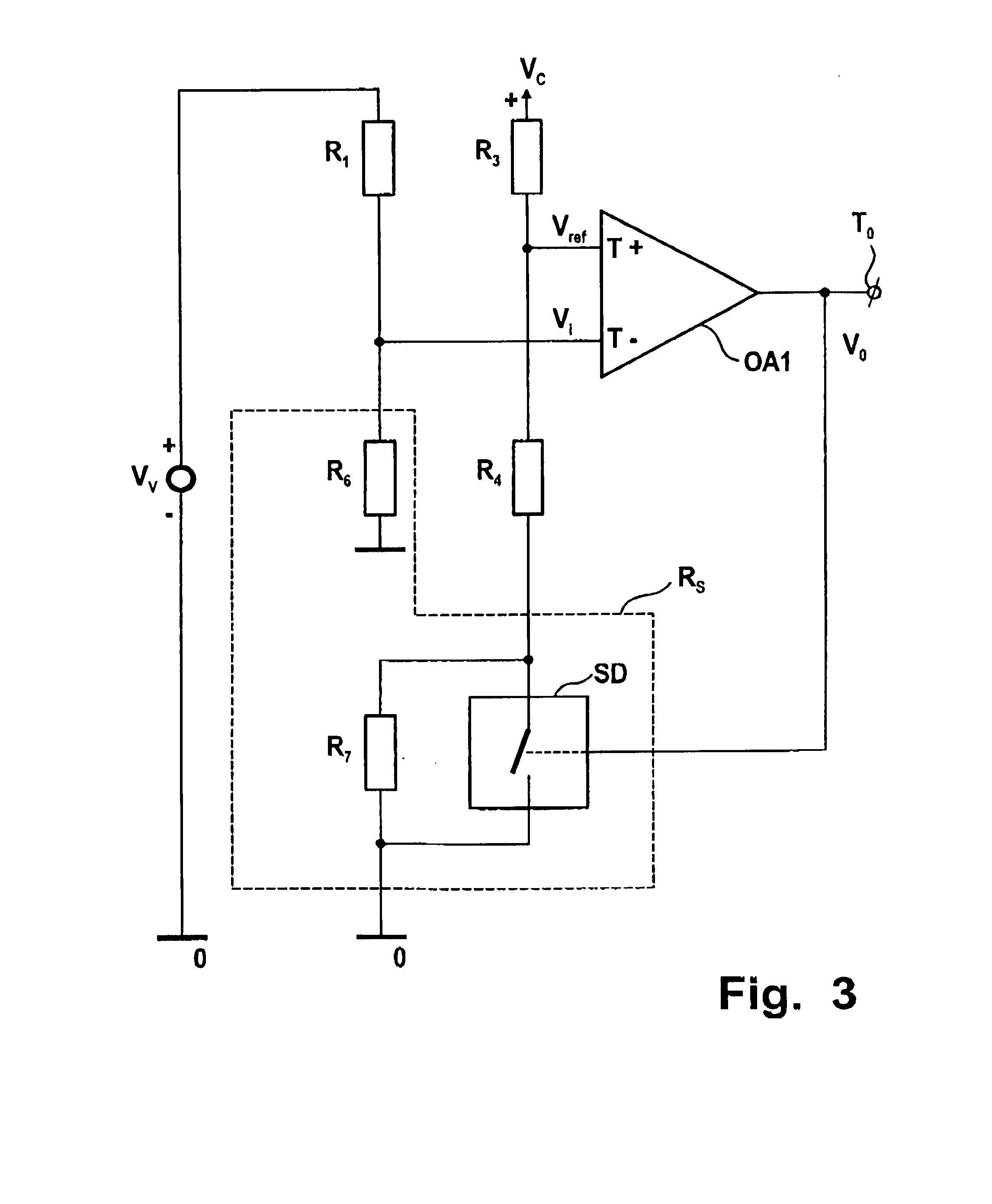
[0044] The circuit has a first operational amplifier having a differential input, first and second voltage dividers being coupled to respectively a variable and a constant voltage source, outputs thereof being coupled to said differential input for supplying a differential input voltage thereto, the first operational amplifier having an output being coupled to its differential input and providing an output voltage stepwise varying between first and second voltage levels at an inversion of the differential input voltage. Such comparator circuit is on itself known e.g. as Schmitt trigger, and is to compare an input voltage with a reference voltage, therewith operating as a voltage level detector.

[0045] FIG. 3 shows an embodiment of a comparator circuit according to the invention, in which--unlike the conventional compa...


PUM


Abstract

A comparator circuit and voltage level detector comprising such comparator circuit including a first operational amplifier having a differential input, first and second voltage dividers being coupled to, respectively, a variable and a constant voltage source, outputs thereof being coupled to the differential input for supplying a differential input voltage thereto. The first operational amplifier having an output being coupled to its differential input and providing an output voltage stepwise varying between first and second voltage levels at an inversion of the differential input voltage. In order to lower power consumption and increase the accuracy of level detection, one of the first and second voltage dividers is being provided with a stepwise variable voltage dividing factor, which is controlled by the output voltage of the first operational amplifier to increase the magnitude of the differential input voltage by a step value upon such inversion of the differential input voltage.

Description

CLAIM FOR PRIORITY[0001] This application claims priority to Application No. EP 01103429.5 which was published in the English language on Feb. 14, 2001.TECHNICAL FIELD OF THE INVENTION[0002] The invention relates to a comparator circuit, and in particular, to a comparator circuit to lower power consumption and increase the accuracy of level detection.BACKGROUND OF THE INVENTION[0003] FIG. 1 illustrates a conventional comparator circuit. As shown therein, the comparator circuit includes an operational amplifier, hereinafter referred to as first operational amplifier OA1, a differential input comprising an inverting and a non-inverting input terminal T- and T+, respectively. The inverting and non-inverting input terminals, T- and T+, are supplied with an input voltage Vi and a reference voltage Vref derived from a variable and a constant voltage source Vv and Vc through first and second voltage dividers, respectively. The first voltage divider comprises a serial arrangement of resisto...

Claims


Application Information

Patent Timeline
IPC IPC(8): G01R19/165H03K3/0233
CPCG01R19/16566H03K3/02337
Inventor DUNNEBACKE, JOACHIMSCHNABEL, STEFFEN
Owner SIEMENS AG
Why Eureka
Try Eureka