Method of driving matrix type display apparatus, display apparatus and electronic equipment

a display apparatus and matrix technology, applied in the direction of instruments, computing, electric digital data processing, etc., can solve the problems of complex configurations of voltage generation circuits and scanning line driving circuits, ineffective reduction of power consumption against all expectations, and complex circuits of apparatuses, so as to reduce power consumption, enhance the likelihood of short circuit in wiring, and simplify manufacturing processes

Inactive Publication Date: 2002-09-12
SEIKO EPSON CORP
View PDF0 Cites 41 Cited by
  • Summary
  • Abstract
  • Description
  • Claims
  • Application Information

AI Technical Summary

Benefits of technology

0023] Furthermore, according to the present invention, preferably, the matrix type display apparatus may further include a gray scale level control signal generating circuit for generating a gray scale level control signal. Further, preferably, when the scanning line of the first region is selected, the data line driving circuit supplies display data to pixels placed on the scanning line by modulating the display data so that the modulated display data corresponds to a gray scale level at which data is displayed, at each of the pixels, according to timing provided by the gray scale level control signal. Moreover, preferably, when the scanning line of the second region is selected, the gray scale level control signal generating circuit stops generating a gray scale level control signal, and the data line driving circuit stops modulating the display data. With this configuration, in the case that there is no need for displaying the data, the generation of the gray scale level control signal is stopped. Furthermore, an operation of modulating a signal corresponding to a gray scale level is stopped. Thus, the power consumption is reduced still more.
0024] Further, according to the present invention, preferably, the switching device is a two-terminal switching device. Moreover, preferably, an electro-optical material is sandwiched between a pair of substrates. Furthermore, preferably, each of the pixels is constituted by series-connecting the two-terminal switching device and the electro-optical material between the plurality of scanning lines provided on one of the pair of substrates and the plurality of data lines. The apparatus of the present invention may use a three-terminal device, for instance, a transistor, as the switching device. However, there is the necessity for forming the scanning lines and the data lines in such a way as to intersect one another on one of the substrates. Thus, such an apparatus has a defect in that the likelihood of an occurrence of a short circuit in the wiring is enhanced. Moreover, the manufacturing process is complexed. In contrast, when the two-terminal switching device is used, the scanning lines are formed on one of the substrates, while the data lines are formed on the other substrate. Thus, the apparatus of this configuration has an advantage in that no short circuits are caused in the wiring in principle. Further, the manufacturing process can be simplified as compared with that in the case of using the three-terminal switching device.
0025] Furthermore, according to the present invention, preferably, the two-terminal switching device has a conductor / insulator / conductor structure connected to the scanning line or the data line. The conductor, which is the first layer, can be used as the scanning line or the data line, without any change. Further, the insulator is formed by anodizing this conductor, that is, the first layer. Consequently, the manufacturing process is simplified still more.
0026] Additionally, to achieve the object, there is provided electronic equipment that may include the aforementioned matrix type display apparatus. Therefore, as described above, this electronic equipment can prevent an occurrence of degradation in the quality of picture, and enhance the resolution thereof, and simplify the configuration thereof.

Problems solved by technology

However, there has occurred a problem that power consumption is ineffectively reduced against all expectation even when only a partial region of the screen of a display apparatus is indicated in the case that a high resolution is not required.
Further, the configuring of the display apparatus in such a way as to display only a part of the screen thereof and to put the remaining region of the screen thereof into a non-display state causes another problem in that the circuit of the apparatus is complex.
Thus, the configurations of the voltage generating circuit and the scanning line driving circuit are complex.

Method used


Image

  • Method of driving matrix type display apparatus, display apparatus and electronic equipment
  • Method of driving matrix type display apparatus, display apparatus and electronic equipment
  • Method of driving matrix type display apparatus, display apparatus and electronic equipment

Examples


Embodiment Construction

[0044] Hereinafter, an embodiment of the present invention is described with reference to the accompanying drawings.

[0045] Electrical Configuration

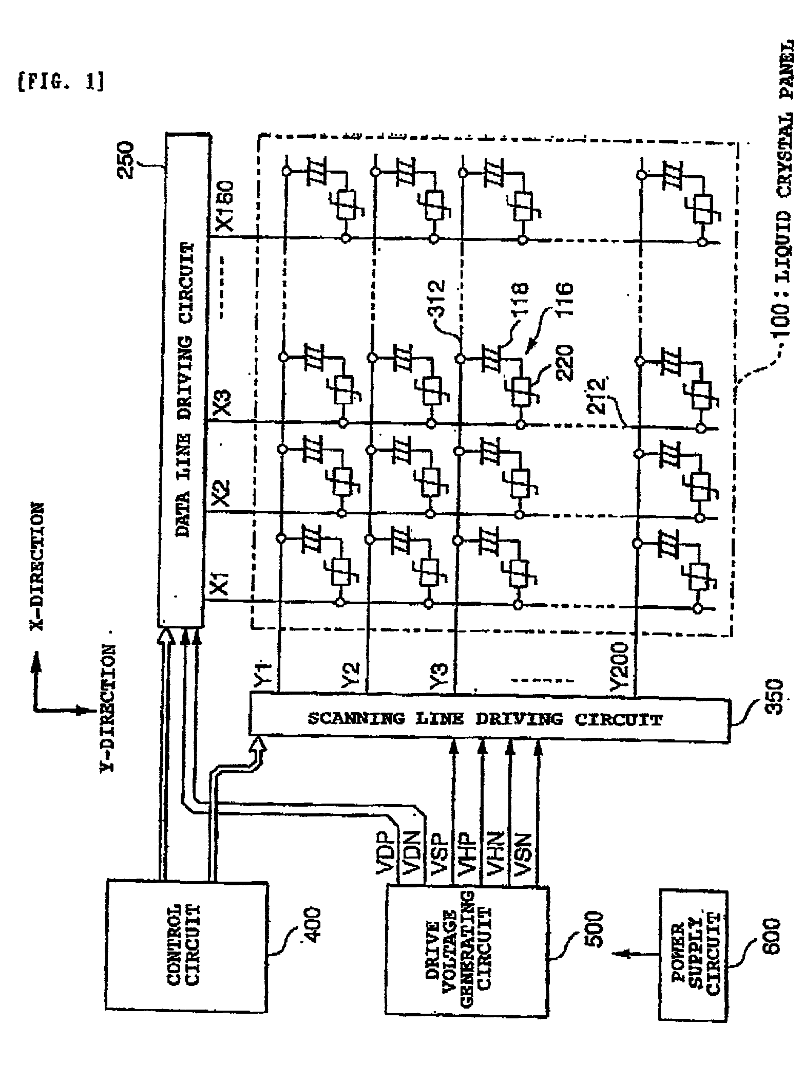
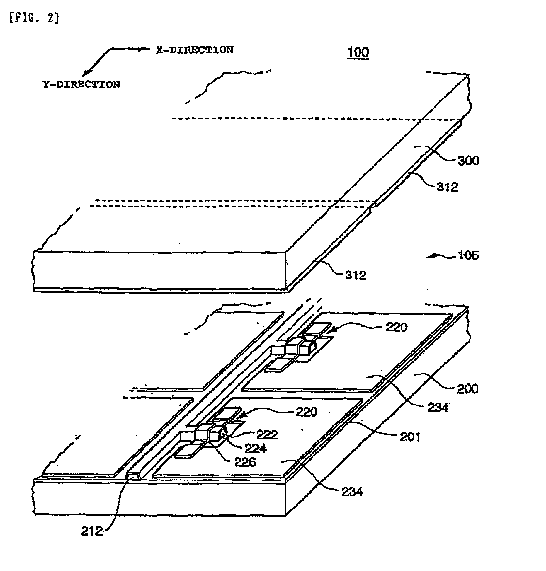
[0046] First, the electrical configuration of a display apparatus according to an embodiment of the present invention is described hereinbelow. FIG. 1 is a block diagram illustrating this electrical configuration. As illustrated in this figure, a liquid crystal panel 100 has a plurality of data lines (or segment electrodes) 212 formed in such a way so as to extend in a column direction (namely, the Y-direction), a plurality of scanning lines (or common electrodes) 312 formed in such a way as to extend in a line direction (namely, the X-direction), and pixels 116 formed respectively corresponding to intersections of the data lines 212 and the scanning lines 312. Further, each of the pixels 116 consists of an electro-optical material (namely, a liquid crystal layer) 118 and a two-terminal switching device 220 (hereunder referred to as a TFD...


PUM

PropertyMeasurementUnit
frequencyaaaaaaaaaa
frequencyaaaaaaaaaa
voltageaaaaaaaaaa

Abstract

It is to manage both the reduction of power consumption and the enhancement of quality of picture when a partial display operation is performed. A scanning line driving circuit 350 supplies each of scanning lines 312 in a display region with selection signals in a second half part of one horizontal scanning time period and with non-selection signals in the rest thereof by inverting the polarity every vertical scanning time period. Further, the scanning line driving circuit 350 supplies each of scanning lines 312 in a non-display region with non-selection signals by inverting the polarity every one or more vertical scanning time periods. A data line driving circuit 250 supplies each of data lines 212 with a signal representing a positive-side voltage level VDP and a signal representing a negative-side voltage level VDN in first and second half parts of a horizontal scanning time period, respectively, for a period of time of the same length in the case that a scanning line 312 in a display region is selected. Furthermore, the data line driving circuit 250 supplies each of data lines 212 alternately with a signal representing the positive-side voltage level VDP and a signal representing the negative-side voltage level VDN every one or more horizontal scanning time period.

Description

BACKGROUND OF THE INVENTION[0001] 1. Field of Invention[0002] The present invention generally relates to a method of driving a matrix type display apparatus which suppresses an occurrence of degradation in quality of picture and which reduces the power consumption to an extremely low value, and to such a matrix type display apparatus and electronic equipment.[0003] 2. Description of Related Art[0004] In display apparatuses used in portable electronic equipment, such as a hand-portable telephone set, the number of display dots has increased year after year so that more information can be displayed on the screen thereof. On the other hand, the portable electronic equipment is battery driven in principle, and thus required to reduce the power consumption thereof as much as possible. Therefore, the display apparatus used in the portable type electronic equipment is required to have two apparently contradictory features, that is, high resolution and low power consumption. Thus, to solve ...

Claims


Application Information

Patent Timeline
Patent Type & Authority Applications(United States)
IPC IPC(8): G02F1/133G02F1/136G02F1/1365G09G3/20G09G3/36
CPCG09G3/2014G09G3/3614G09G3/367G09G2310/0232G09G2330/021
Inventor INOUE, AKIRAYAMAZAKI, SUGURU
Owner SEIKO EPSON CORP
Why Eureka
Try Eureka