
Method and apparatus for filtering an optical beam

Inactive Publication Date: 2002-09-12
INTEL CORP
View PDF18 Cites 97 Cited by
  • Summary
  • Abstract
  • Description
  • Claims
  • Application Information

AI Technical Summary

Benefits of technology

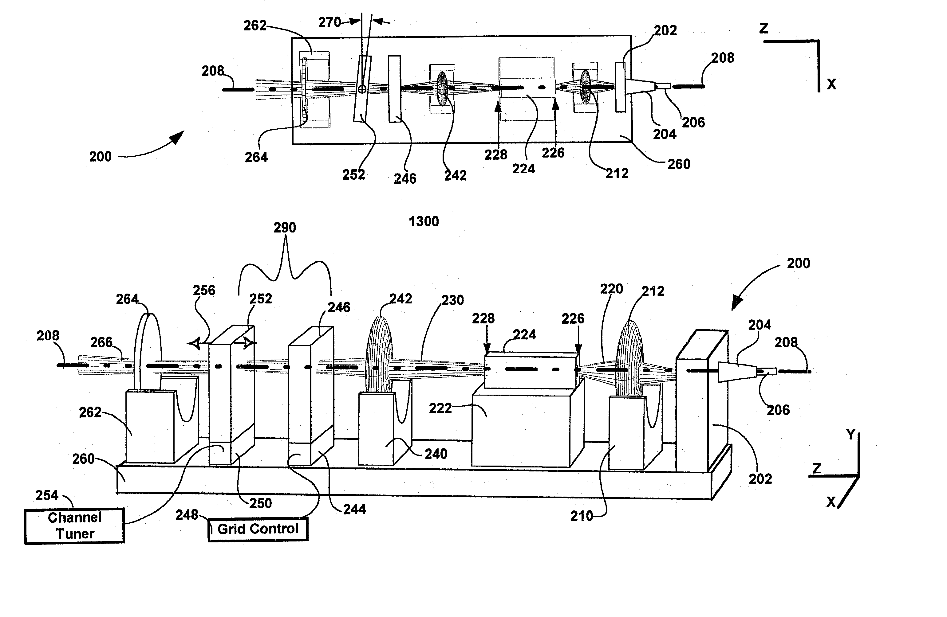
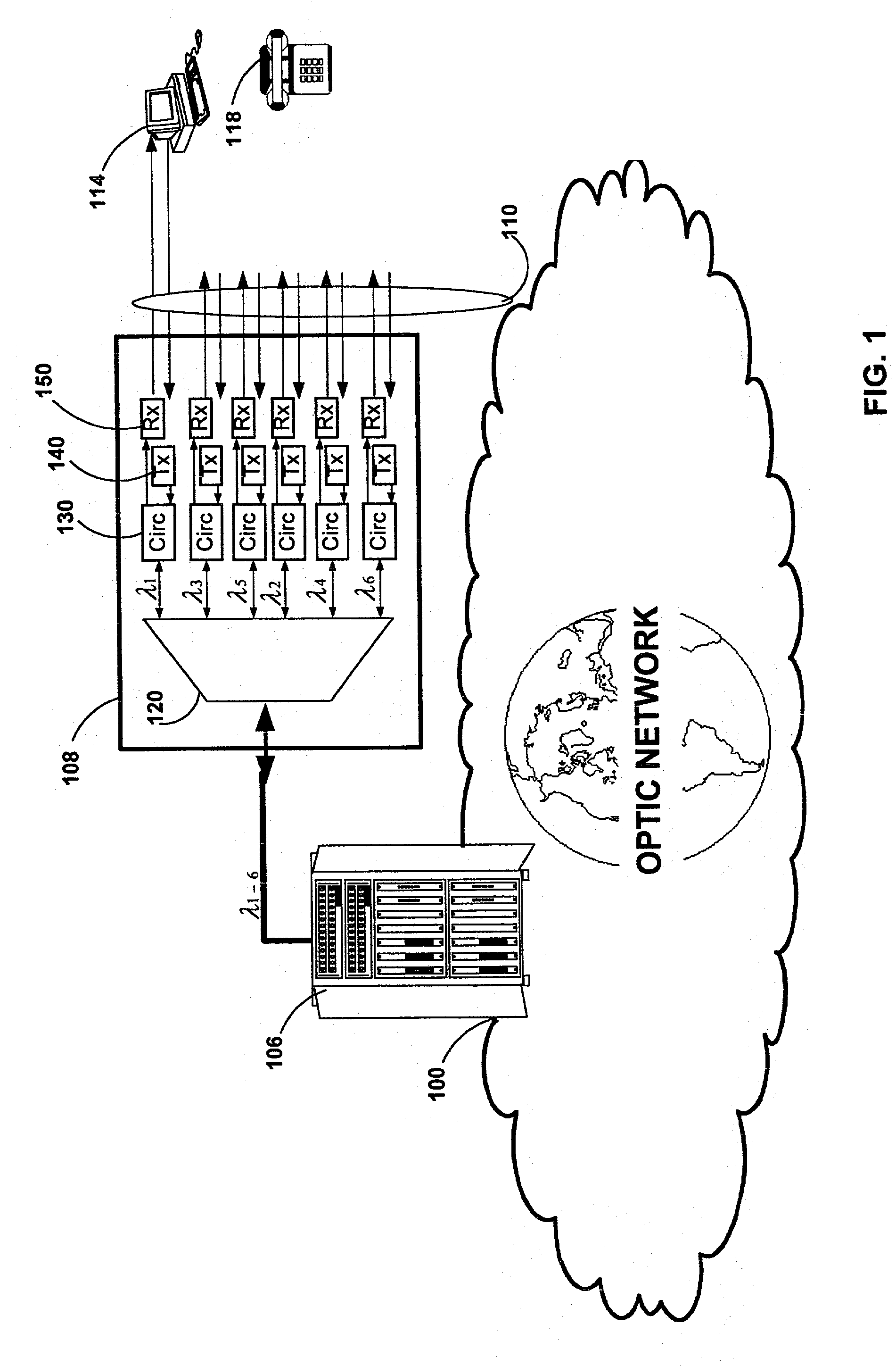
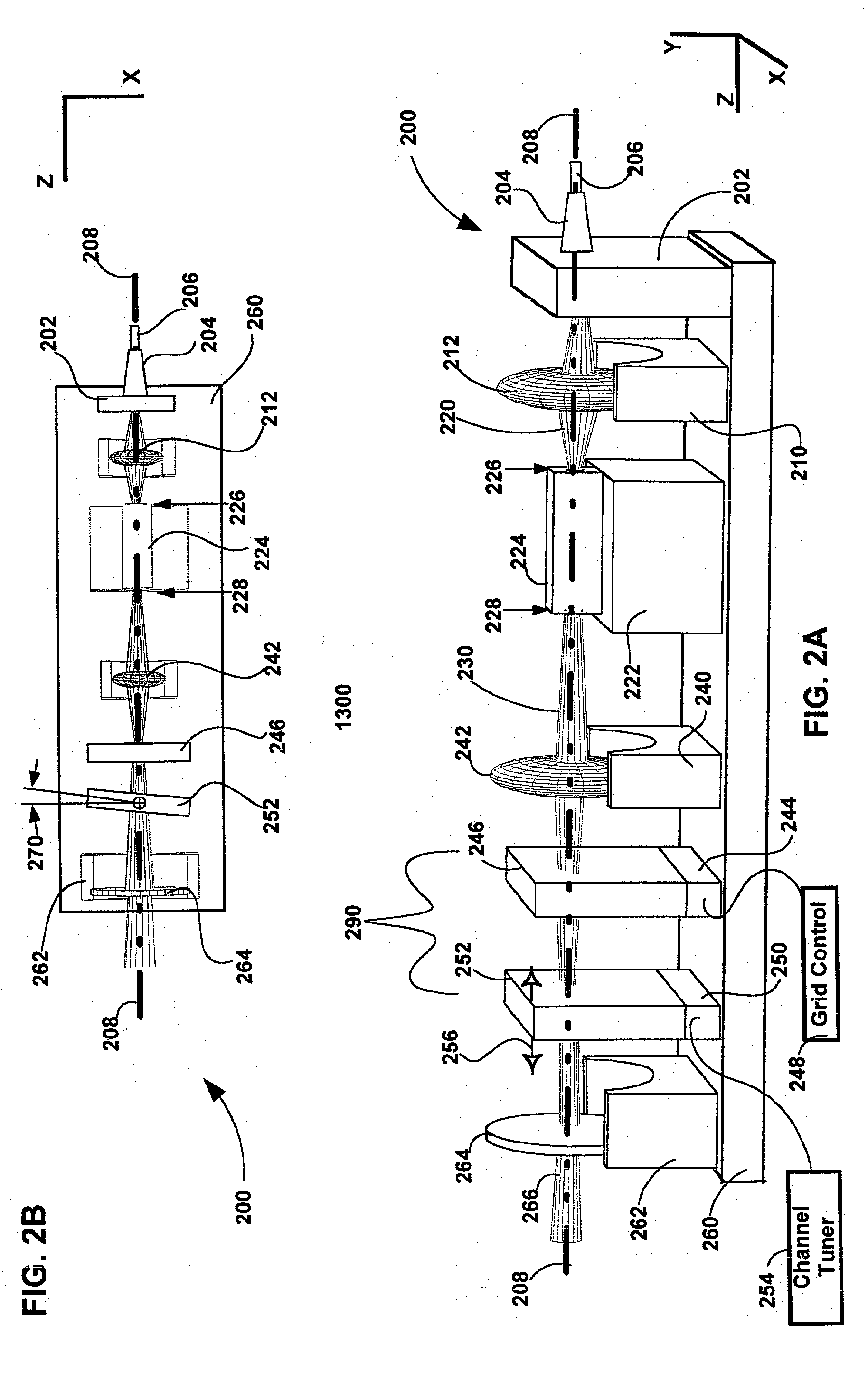
[0012] The invention pertains to wavelength-agile optical filters suitable for wavelength-division-multiplexed (WDM) optical communications networks. More particularly, the invention pertains to optical filters with a wavelength reference that can be remotely switched to arbitrarily selectable channels on a standard grid, and to re-configurable optical communications networks employing same. The present invention provides a communication apparatus with a tunable filter which may be used in a wide range of applications including tuning an external cavity laser (ECL), selecting a wavelength for an add / drop multiplexer and providing channel selection and feedback for a wavelength locker. The filter may be utilized as a discrete component or in combination with circulators, wavelength lockers and gain medium. The filter may be implemented in whole or in part as part of a gain medium. The tunable filter exhibits a compact form factor and precise tuning to any selected wavelength of a predetermined set of wavelengths comprising a wavelength grid. The tunable filter may thus be utilized in telecom applications to generate the center wavelengths for any channel on the ITU or other optical grid.

Problems solved by technology

DFB lasers suffer from the drawback that they have small tuning ranges of .about.3 nm (See, e.g., J. Carroll, J. Whiteaway, & D. Plumb, Distributed feedback semiconductor lasers, SPIE Press, 1998).
As a result, DFB laser transmitters cannot be assigned to arbitrary channels.

Method used


Image

  • Method and apparatus for filtering an optical beam
  • Method and apparatus for filtering an optical beam
  • Method and apparatus for filtering an optical beam

Examples


Embodiment Construction

[0025] The invention pertains to wavelength-agile optical filters suitable for wavelength-division-multiplexed (WDM) optical communications networks. More particularly, the invention pertains to optical filters with a wavelength reference that can be remotely switched to arbitrarily selectable channels on a standard grid, and to re-configurable optical communications networks employing same. The present invention provides a communication apparatus with a tunable filter which may be used in a wide range of applications including tuning an external cavity laser (ECL), selecting a wavelength for an add / drop multiplexer and providing channel selection and feedback for a wavelength locker. The tunable filter may thus be utilized in telecom applications to generate the center wavelengths for any channel on the ITU or other optical grid.

[0026] A novel tuning mechanism is disclosed which provides for electrical or mechanical tuning to a known position or electrical parameter, e.g., voltage,...


PUM


Abstract

The invention pertains to wavelength-agile optical filters suitable for wavelength-division-multiplexed (WDM) optical communications networks. More particularly, the invention pertains to optical filters with a wavelength reference that can be remotely switched to arbitrarily selectable channels on a standard grid, and to re-configurable optical communications networks employing same. The present invention provides a communication apparatus with a tunable filter which may be used in a wide range of applications including tuning an external cavity laser (ECL), selecting a wavelength for an add / drop multiplexer and providing channel selection and feedback for a wavelength locker. The filter may be utilized as a discrete component or in combination with circulators, wavelength lockers and gain medium. The filter may be implemented in whole or in part as part of a gain medium. The tunable filter exhibits a compact form factor and precise tuning to any selected wavelength of a predetermined set of wavelengths comprising a wavelength grid. The tunable filter may thus be utilized in telecom applications to generate the center wavelengths for any channel on the ITU or other optical grid.

Description

CROSS REFERENCE TO RELATED APPLICATIONS[0001] This application claims the benefit of prior filed U.S. Provisional Application No. 60 / 145,831 filed on Jul. 27, 1999 entitled "VERNIER TUNED ECDL" by inventor Evan D. H. Green which is incorporated herein by reference in its entirety.BACKGROUND OF THE INVENTION[0002] 1. Field of Invention[0003] The invention pertains to wavelength-agile optical filters suitable for wavelength-division-multiplexed (WDM) optical communications networks. More particularly, the invention pertains to optical filters with a wavelength reference that can be remotely switched to arbitrarily selectable channels on a standard grid, and to re-configurable optical communications networks employing same.[0004] 2. Description of the Related Art[0005] The telecommunications network serving the United States and the rest of the world is presently evolving from analog to digital transmission with ever increasing bandwidth requirements. Fiber optic cable has proved to be...

Claims


Application Information

Patent Timeline
IPC IPC(8): G02B5/28G02B6/34G02B7/00G02B26/00H01S5/022H01S5/0687H01S5/14H04J14/02
CPCG02B5/281G02B5/284G02B6/29358G02B6/29361G02B6/29395G02B26/002G02B26/007H01S3/1062H01S5/02248H01S5/02284H01S5/0687H01S5/141H04J14/02H01S5/02251H01S5/02325
Inventor GREEN, EVAN D.H.CHAPMAN, WILLIAM B.
Owner INTEL CORP
Learn More