Housing for electronic apparatus having outer wall formed by injection molding

an electronic apparatus and injection molding technology, which is applied in the direction of metal rolling stands, metal casings, emergency protective circuit arrangements, etc., can solve the problems of magnesium alloy not being able to fully fill the entire mold space, affecting the production efficiency of the electronic apparatus, and deteriorating the fluidity of magnesium alloy, etc., to achieve the effect of reducing production costs and increasing productivity

Inactive Publication Date: 2002-09-12
KK TOSHIBA
View PDF9 Cites 72 Cited by
  • Summary
  • Abstract
  • Description
  • Claims
  • Application Information

AI Technical Summary

Benefits of technology

0010] The present invention has been achieved under the above-described circumstances, and the object thereof is to provide a high-quality housing

Problems solved by technology

Therefore, when injecting a magnesium alloy into the mold space, a high resistance is imparted to the magnesium alloy flowing in the mold space, and therefore the fluidity of the magnesium alloy is deteriorated.
If the fluidity of the magnesium alloy within the mold space is poor, it is possible that the magnesium alloy cannot fully fill the entire mold space in the case of an A4-sized area, which is larger than, for example, a B5-sized area, even though no errors occur in a B5-sized area case in the

Method used


Image

  • Housing for electronic apparatus having outer wall formed by injection molding
  • Housing for electronic apparatus having outer wall formed by injection molding
  • Housing for electronic apparatus having outer wall formed by injection molding

Examples


Embodiment Construction

[0021] Embodiments of the present invention will now be described with reference to drawings in which the present invention is applied to portable computers.

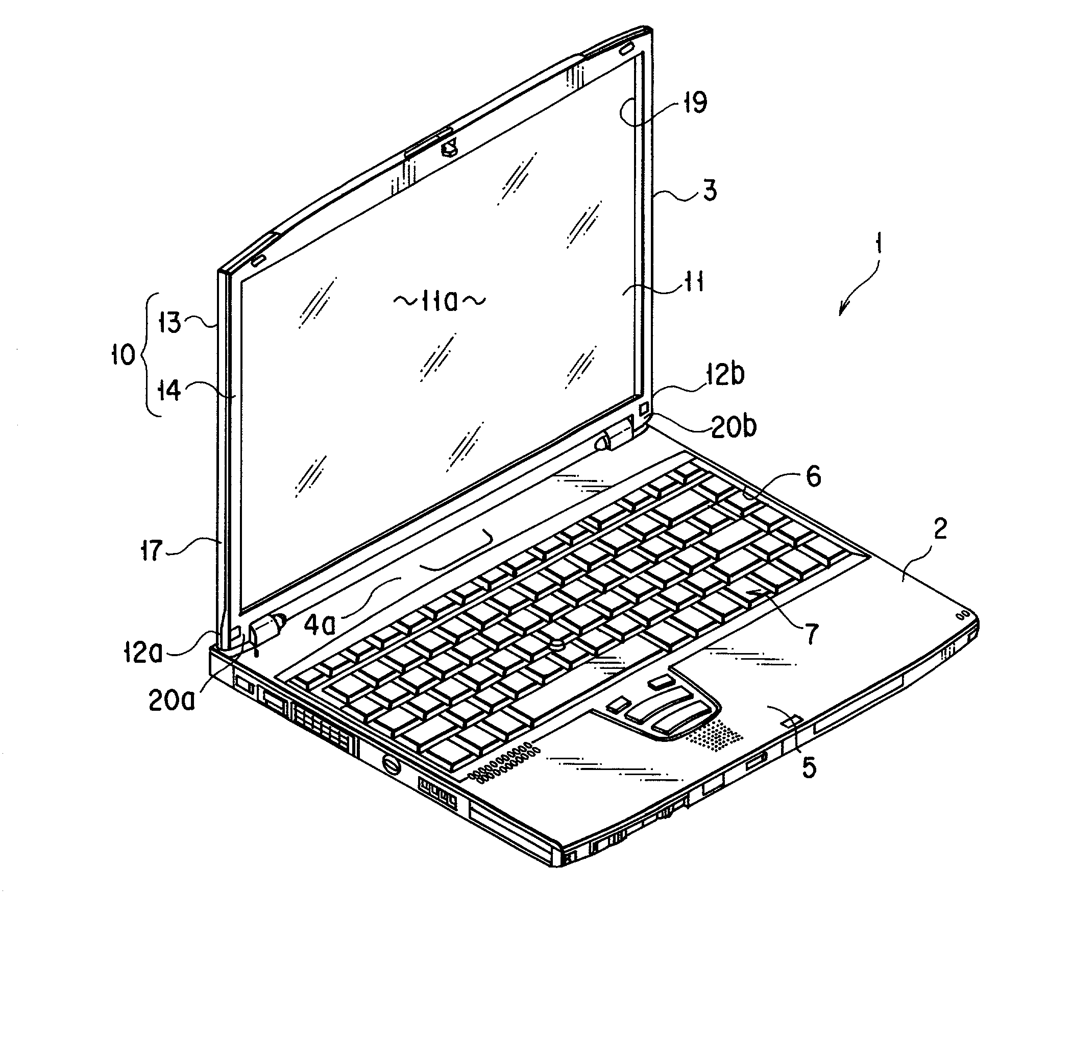
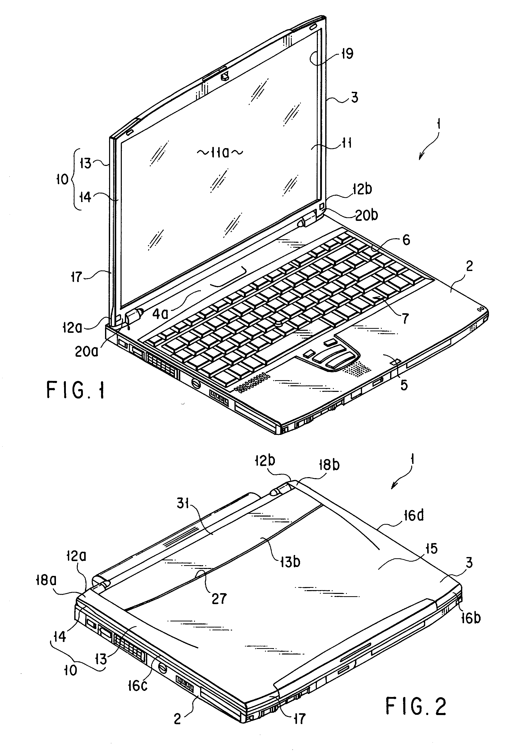
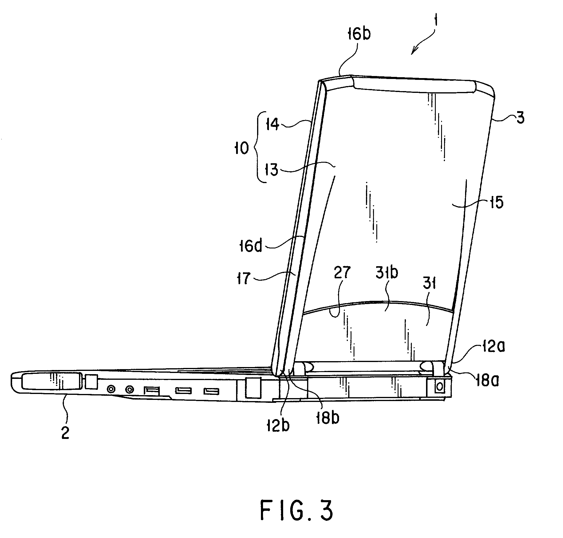
[0022] FIGS. 1 to 3 disclose a portable computer 1 as an electronic apparatus. The portable computer 1 includes a computer main body 2, and a display unit 3 supported by the computer main body 2.

[0023] The computer main body 2 has a flat box shape having a flat upper wall 4a. The upper wall 4a of the computer main body 2 includes a palm rest 5 and a keyboard mount portion 6. The palm rest 5 is situated at a front half section of the computer main body 2. The keyboard mount portion 6 is situated on the back of the palm rest 5. A keyboard 7 is provided in the keyboard mount portion 6.

[0024] The display unit 3 includes a display housing 10 and a liquid crystal display panel 11 as the functional part. The display housing 10 has a pair of leg portions 12a and 12b at one end. The leg portions 12a and 12b are provided to be apart from ...


PUM


Abstract

The housing used in the electronic apparatus has an outer wall. The outer wall is formed by injecting a metal material from a plurality of gates into a molding space in a metal die. The outer wall includes a first end portion situated on an upstream end along a flowing direction of the metal material, a second end portion situated on a downstream end of the flowing direction of the metal material, and an injection portion formed on the first end portion where the plurality of gates of the metal die are situated, forming a space between the first end portion and the injection portion.

Description

CROSS-REFERENCE TO RELATED APPLICATIONS[0001] This application is based upon and claims the benefit of priority from prior Japanese Patent Application No. 2001-063960, filed Mar. 7, 2001.BACKGROUND OF THE INVENTION[0002] 1. Field of the Invention[0003] The present invention relates to a housing used for an electric apparatus, such as a portable computer, and more specifically, to such a structure that provides for thinner housings.[0004] 2. Description of the Related Art[0005] An important factor for raising the commercial value of an electronic apparatus, such as a portable computer, is that it is compact and has excellent portability. Therefore, with regard to the housing enclosing various types of electronic devices, such as a hard disk drive device and a liquid crystal display panel, it is desired that the thickness of the housing be reduced as much as possible while maintaining the strength, rigidity and appearance of the apparatus.[0006] In order to achieve the above, a magnes...

Claims


Application Information

Patent Timeline
IPC IPC(8): B22C9/06B22C9/08B22C9/22B22D21/04B22D17/00B22D17/22G06F1/16H05K5/04
CPCB22D17/007B22D17/22G06F1/1616G06F1/1656Y10T29/4998
Inventor MINAGUCHI, HIROYUKITAJIMA, NOBUYASUYOKOYAMA, NAOHIROSUZUKI, YASUYUKI
Owner KK TOSHIBA
Why Eureka
Try Eureka