Dual filament, electrostatically controlled focal spot for x-ray tubes

Inactive Publication Date: 2002-09-12
KONINKLIJKE PHILIPS ELECTRONICS NV +1
View PDF0 Cites 66 Cited by
  • Summary
  • Abstract
  • Description
  • Claims
  • Application Information

AI Technical Summary

Benefits of technology

0013] One advantage of the present invention resides in obtaining a higher x-ray flux without overheating the anode track.
0014] Another advantage of the present invention is that it produces x-ray radiation having multiple focal spot lengths.
0015] Another advantage of the present invention resides in the presence of multiple filaments without additional external connections between the x-ray tube and the CT

Problems solved by technology

While the electrostatic method yields greater focal position control, it is limited to providing a focal spot of a single length.
While the magnetic yoke method employs two filaments, therefore providing two focal spot lengths and widths, it is disadvantageous for a number of reasons.
The magnetic yoke tube require

Method used


Image

  • Dual filament, electrostatically controlled focal spot for x-ray tubes
  • Dual filament, electrostatically controlled focal spot for x-ray tubes
  • Dual filament, electrostatically controlled focal spot for x-ray tubes

Examples


Embodiment Construction

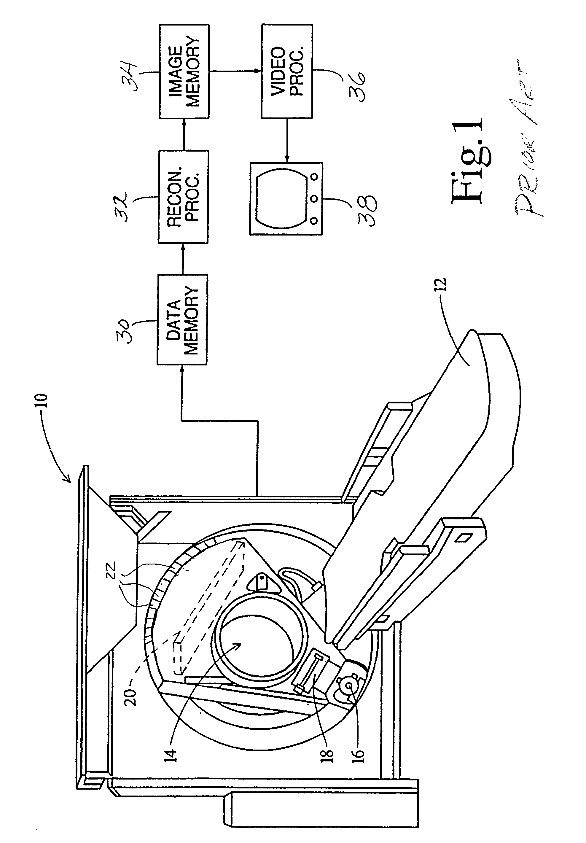
[0028] With reference to FIG. 1, a computerized tomographic (CT) scanner 10 radiographically examines and generates diagnostic images of a subject disposed on a patient support 12. More specifically, a volume of interest of the subject on the support 12 is moved into an examination region 14. An x-ray tube assembly 16 mounted on a rotating gantry projects one or more beams of radiation through the examination region 14. A collimator 18 collimates the beams of radiation in one dimension. In third generation scanners, a two-dimensional x-ray detector 20 is disposed on the rotating gantry across the examination region 14 from the x-ray tube. In fourth generation scanners, a ring or array of two-dimensional detectors 22 is mounted on the stationary gantry around the rotating gantry.

[0029] Each of the two-dimensional x-ray detectors 20, 22 includes a two-dimensional array of photodetectors connected or preferably integrated into an integrated circuit. The detectors generate electrical si...


PUM


Abstract

A dual filament x-ray tube assembly (16) includes an evacuated envelope (52) having an anode (54) disposed at a first end of the evacuated envelope (52) and a cathode assembly (62) disposed at a second end of the evacuated envelope (52). The cathode assembly includes a variable-length filament assembly (72, 74; 100) which emits electron beams for impingement on the anode (54) at focal spots having varying lengths. The cathode assembly (62) further includes a cathode cup (64, 66, 68; 110, 112) which is subdivided into a plurality of electrically insulated deflection electrodes (64, 66, 68; 110, 112). A filament select circuit (80) selectively and individually heats a portion of the variable-length filament assembly (72, 74). Electron beams emitted from the filament assembly (72, 74) are electrostatically focused and controlled by applying potentials to different ones of the deflection electrodes (64, 66, 68; 110, 112). The x-ray tube assembly (16) provides longer focal spots for thick-slice scanning applications and shorter focal spots for thin-slice scanning applications along with the benefit of electrostatic focusing and control.

Description

BACKGROUND OF THE INVENTION[0001] The present invention relates to the x-ray tube art. It finds particular application in conjunction with high power x-ray tubes for use with CT scanners and the like and will be described with particular reference thereto. It is to be appreciated, however, that the invention will also find application in conjunction with conventional x-ray diagnostic systems and other penetrating radiation systems for medical and non-medical examinations.[0002] Typically, a high power x-ray tube includes an evacuated envelope or housing which holds a cathode filament through which a heating or filament current is passed. A high potential, typically on the order of 100-200 kV, is applied between the cathode and an anode which is also located within the evacuated envelope. This potential causes a tube current or beam of electrons to flow from the cathode to the anode through the evacuated region in the interior of the evacuated envelope. The electron beam impinges on ...

Claims


Application Information

Patent Timeline
IPC IPC(8): H05G1/34H01J35/06H01J35/14H05G1/00
CPCH01J35/06H01J2235/068H01J35/066
Inventor HARRIS, JASON P.PERNO, SALVATORE
Owner KONINKLIJKE PHILIPS ELECTRONICS NV
Why Eureka
Try Eureka