Cathode header optic for x-ray tube

a cathode and x-ray tube technology, applied in the field of x-ray tubes, can solve the problems of cathode optics, relatively difficult to design and manufacture the emitter for use in an inexpensive, miniature x-ray tube, size, energy efficiency, cost and complexity of manufacturing and maintenance of tight manufacturing tolerances, etc., to achieve less affected, reduce electron beam cross-section, and increase electron efficiency

a cathode and x-ray tube technology, applied in the field of x-ray tubes, can solve the problems of cathode optics, relatively difficult to design and manufacture the emitter for use in an inexpensive, miniature x-ray tube, size, energy efficiency, cost and complexity of manufacturing and maintenance of tight manufacturing tolerances, etc., to achieve less affected, reduce electron beam cross-section, and increase electron efficiency

US20090022277A1Active Publication Date: 2009-01-22MOXTEK INC

Image

  • Cathode header optic for x-ray tube
  • Cathode header optic for x-ray tube
  • Cathode header optic for x-ray tube

Examples


Embodiment Construction

)

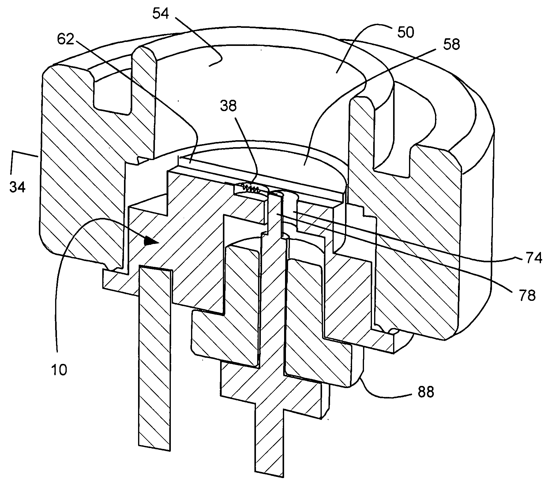
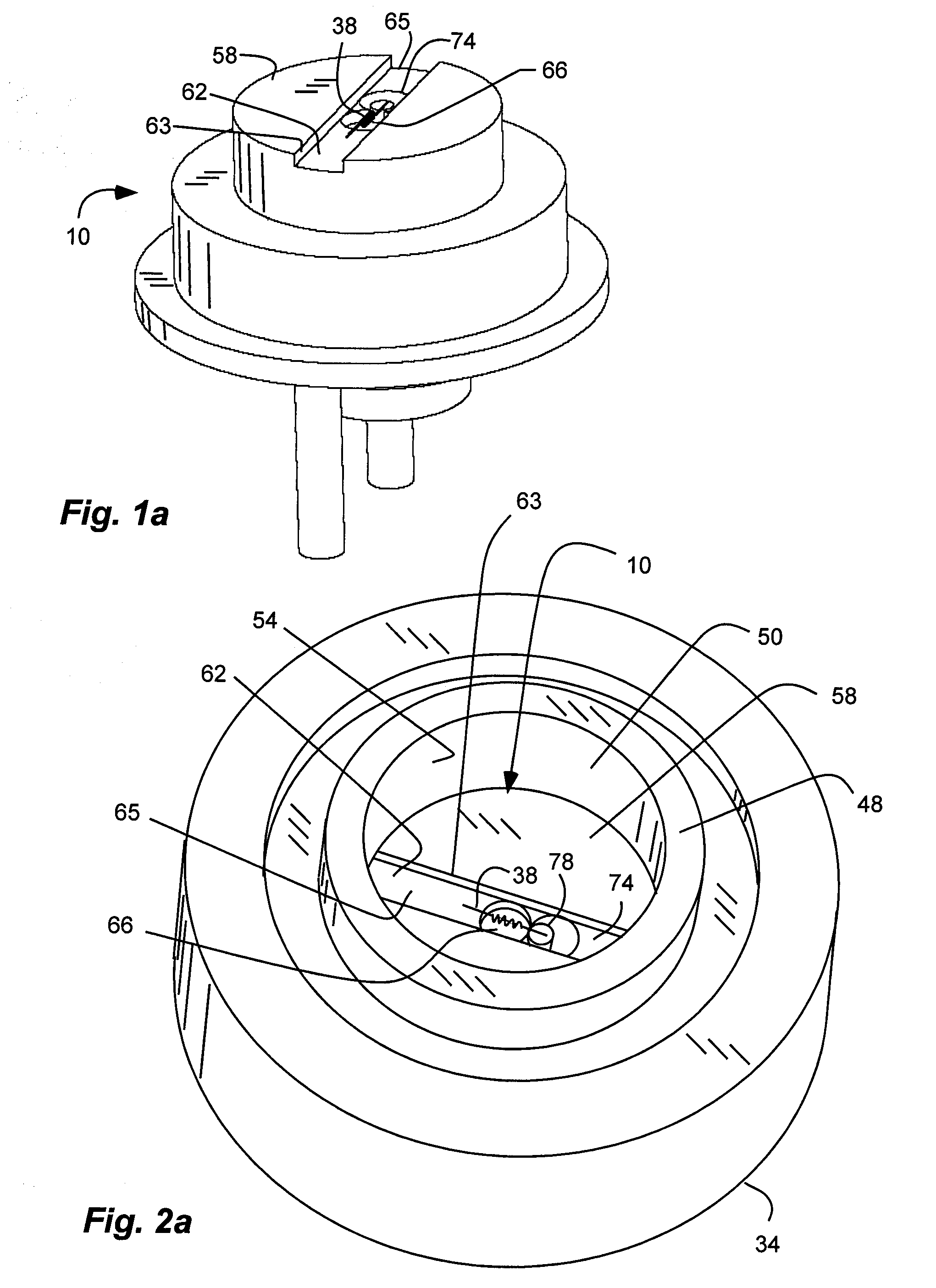
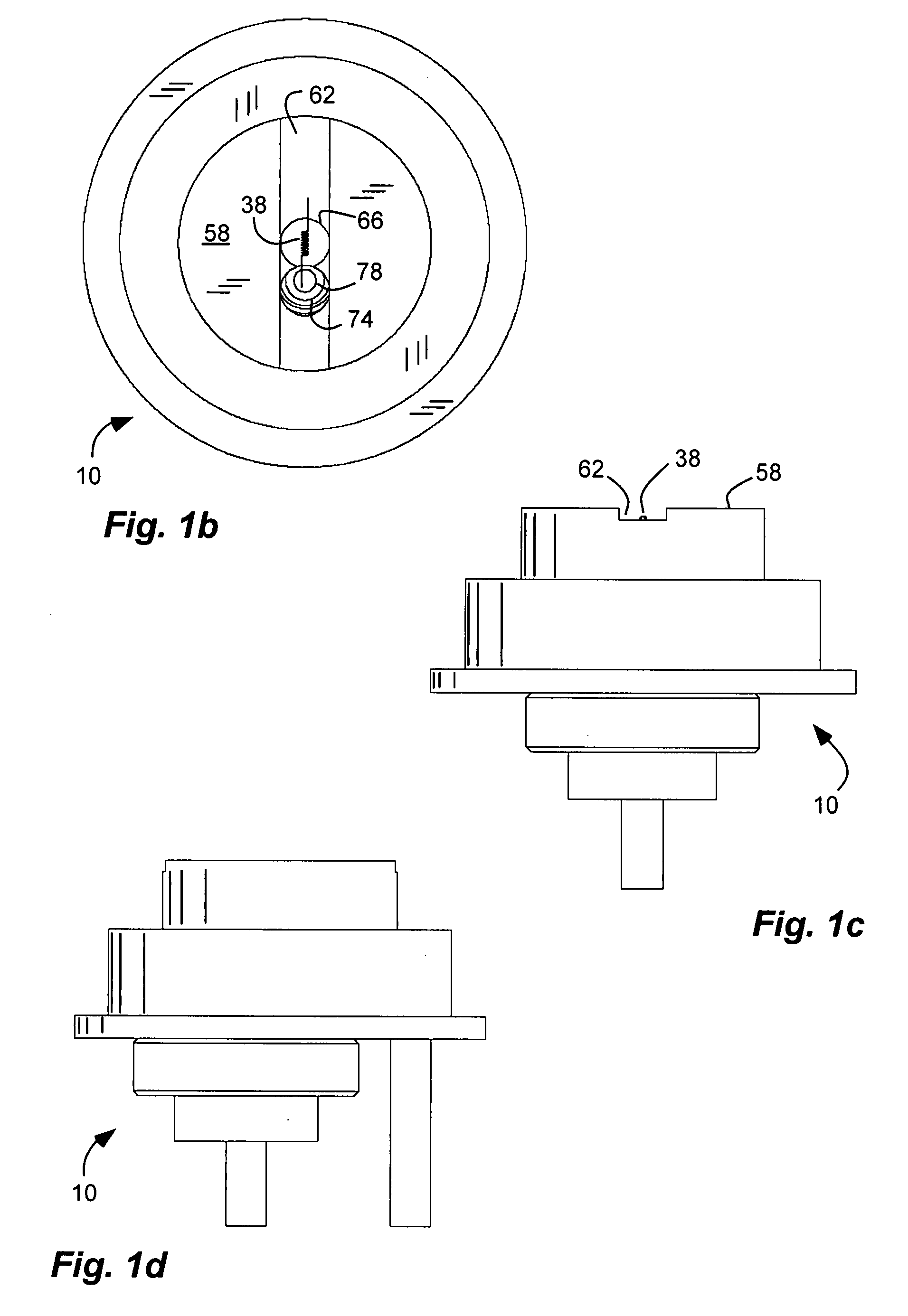
[0034]Referring to FIGS. 1a-2b, an exemplary embodiment of a cathode header optic 10 is shown for an x-ray tube or source 14 (FIG. 4a). The term cathode header optic is used broadly herein to describe the structure carrying the cathode element and which shapes an electric field which shapes an electron beam emitted from the cathode element. The cathode header optic can form a portion of the cathode of the x-ray tube.

[0035]Referring to FIG. 4a, the x-ray tube or source 14 can include an evacuated dielectric tube 18. An anode 22 is disposed at an end of the tube and includes a material configured to produce x-rays (represented by lines 26) in response to impact of electrons (represented by lines 30). A cathode 34 is disposed at an opposite end of the tube opposing the anode. The cathode 34 includes a cathode element 38 (FIG. 1a) configured to produce electrons accelerated towards the anode in response to an electric field between the anode and the cathode. The cathode element 38 can ...


PUM


Abstract

A cathode header optic for an x-ray tube includes an elongate trench with opposite trench walls. A cup recess is formed in the trench between the opposite trench walls, and has a bounded perimeter. A cathode element is disposed in the trench at the cup recess. The cathode element is capable of heating and releasing electrons. A secondary cathode optic defining a cathode ring can be disposed about the header optic. The cathode optics can form part of an x-ray tube.

Description

BACKGROUND[0001]1. Field of the Invention[0002]The present invention relates generally to x-ray tubes and more particularly to cathodes or cathode optics for such x-ray tubes.[0003]2. Related Art[0004]Thermionic emission is a very common strategy for obtaining electrons for use in x-ray producing devices. For thermionic electron emission to take place, a source material is heated to high temperature in an evacuated environment in order to impart sufficient energy to bound electrons within the material to liberate them. The energy required is known as the material “work function.” A thermionic electron source is usually made of tungsten in the form of a filament and is often alloyed with other material(s) to reduce work function and / or to improve mechanical properties of the filament under the rigors of high-temperature operation.[0005]A critical aspect of any x-ray device containing a thermionic (or other) electron source is the performance of its electron optics. In a miniature x-r...

Claims


Application Information

Patent Timeline
22 Jan 2009
Publication
US20090022277A1
IPC
H01J35/14
CPC
H01J35/14; H01J35/06; H01J35/147; H01J35/066
Inventors
BARD, ERIK C.; LIDDIARD, STEVEN D.