
Method of performing x-ray spectroscopy and x-ray absorption spectrometer system

Active Publication Date: 2019-01-10
SIGRAY INC
View PDF0 Cites 18 Cited by
  • Summary
  • Abstract
  • Description
  • Claims
  • Application Information

AI Technical Summary

Benefits of technology

[0011]The disclosed x-ray absorption spectrometer comprises a laboratory x-ray source, and an optical train which focuses x-rays over an energy bandwidth greater than 10 eV emerging from the x-ray source on or near an object to be examined with an focus size less than 500 micrometers. The benefits of the optical train include high x-ray flux on the sample and small illuminated spot for analyzing a small area (high spatial resolution) and use of crystal analyzers with low Bragg angles for high throughput, and compactness of the spectrometer. Additionally, it may also serves as a low-pass filter with a predetermined high-energy cut-off for the x-rays. The benefit of using an optical train that has properties enabling it to serve as low-pass focusing reflector is that the x-ray production efficiency of the x-ray source can be increased by enabling the energy of the bombarding electrons in the x-ray source to be substantially higher.
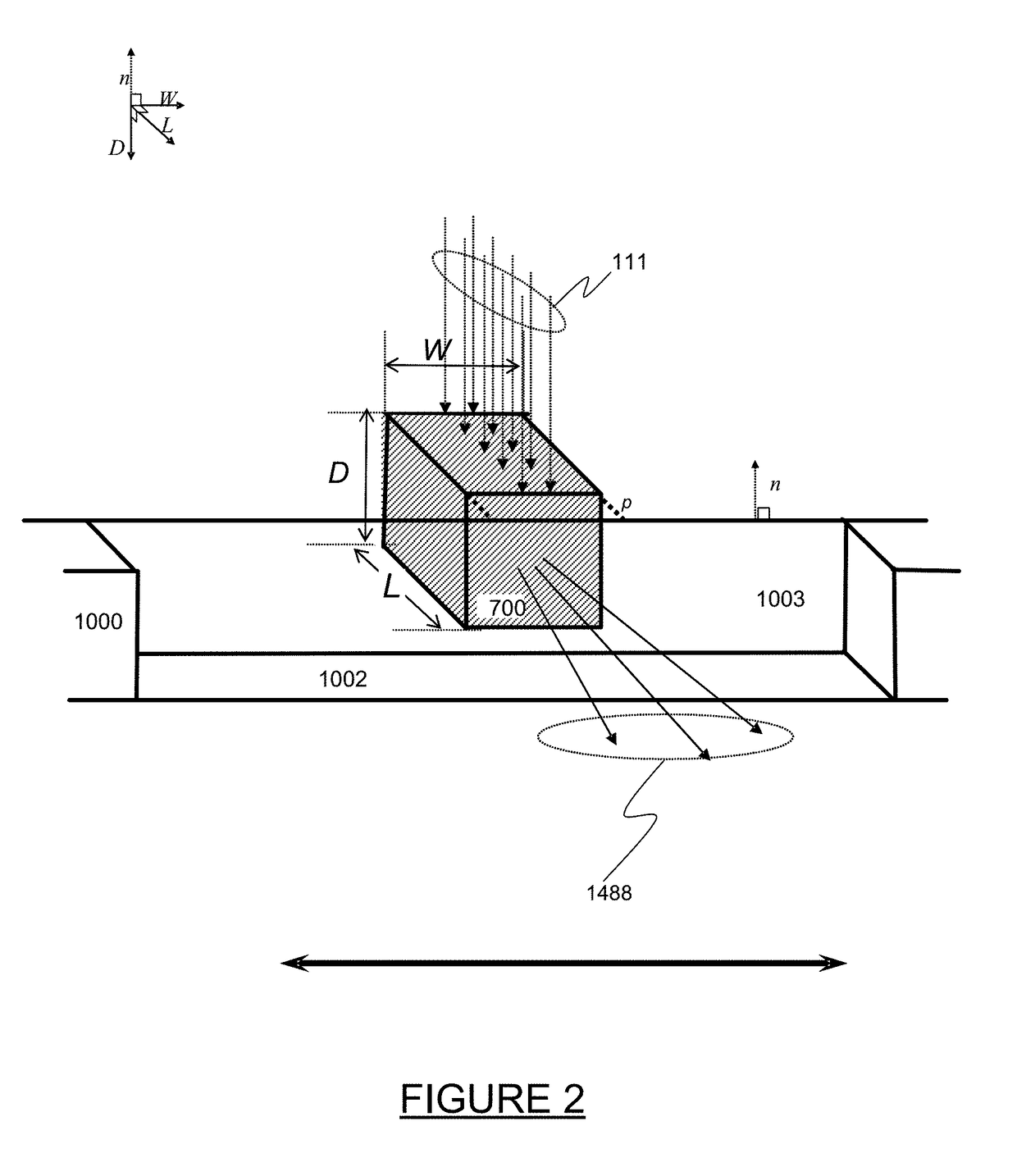
[0014]In some embodiments, the higher brightness compact x-ray source is achieved in part through the use of novel x-ray targets used in generating x-rays from electron beam bombardment. These x-ray target configurations may comprise a number of microstructures of one or more selected x-ray generating materials fabricated in close thermal contact with (such as embedded in or buried in) a substrate with high thermal conductivity, such that the heat is more efficiently removed from the x-ray generating material. This in turn allows bombardment of the x-ray generating material with higher electron density and / or higher energy electrons, which leads to greater x-ray brightness and greater x-ray flux.

Problems solved by technology

X-ray absorption spectroscopy (XAS) is a technique commonly employed at high brightness synchrotron light sources for chemical analysis, but has been limited in its application at the laboratory due to a combination of the long acquisition times needed and poor spectral resolution of laboratory systems.
However, this is generally limited by the ability of the material to absorb energy without melting or damage.
Small laboratory-based x-ray absorption spectroscopy systems would provide easy access and full control; however the performance of laboratory XAS systems has been largely limited by a combination of many factors, including low brightness of the Bremsstrahlung radiation of laboratory x-ray sources, low diffraction efficiency of the crystal analyzer associated with the use of high index reflections, and non-optimal spectrometer design.
Those limitations often result in unacceptably long acquisition times (˜up to tens of hours) and / or poor energy resolution.
As a consequence, there are few laboratory systems in use.
However, that system has several limitations including: there is no focusing optic between the source and object, resulting in low x-ray flux density on the object; need of a large illuminated area to obtain sufficient x-ray flux on the object; as a consequence of the large illuminated area, crystal analyzers need to operate at high Bragg angles to achieve adequate energy resolution; because x-ray energy range for a crystal analyzer operating at high Bragg angles is typically limited to a narrow operating energy range, a large number of crystal analyzers are required for the spectrometer to operate over a sufficiently wide energy bandwidth; because a crystal analyzer operating at high Bragg angles typically reflects an energy bandwidth significantly narrower than the energy resolution required for XAS measurement, it leads to significant loss in measurement throughput.

Method used


Image

  • Method of performing x-ray spectroscopy and x-ray absorption spectrometer system
  • Method of performing x-ray spectroscopy and x-ray absorption spectrometer system
  • Method of performing x-ray spectroscopy and x-ray absorption spectrometer system

Examples


Embodiment Construction

1. A Basic Embodiment of the Invention.

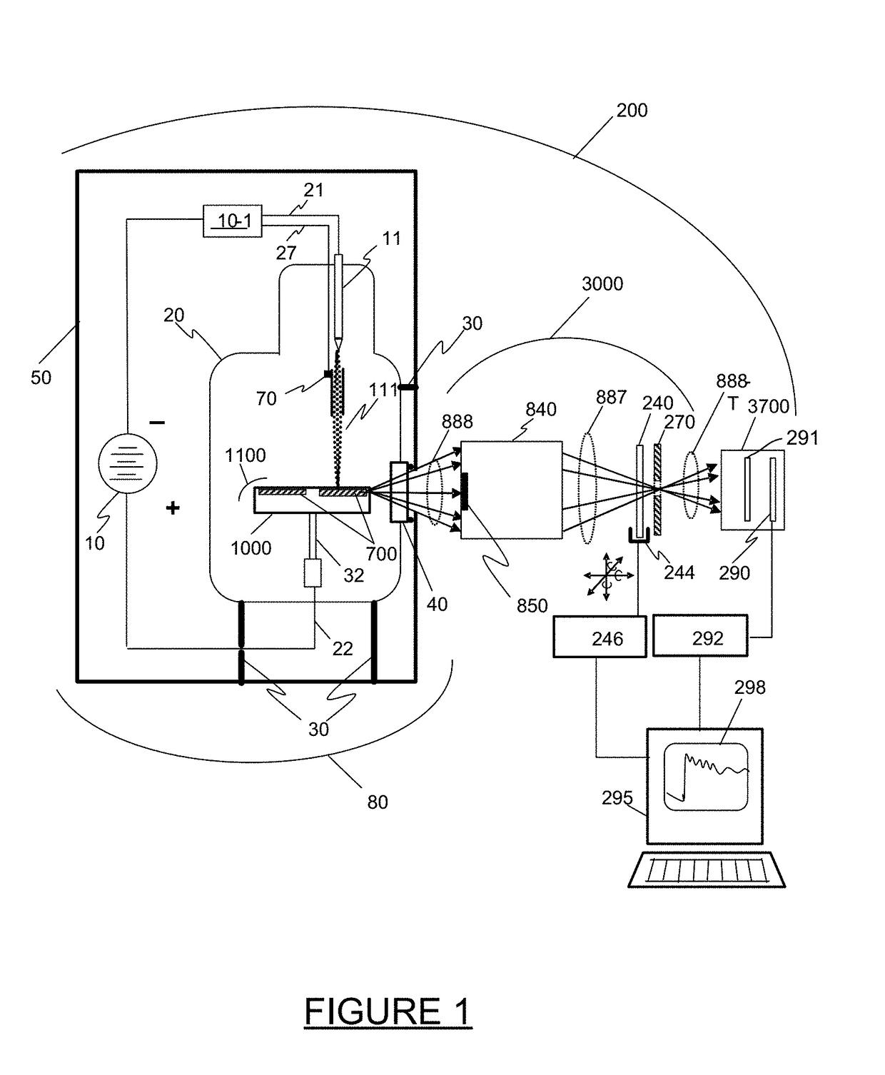
[0036]FIG. 1 illustrates an embodiment of an x-ray spectrometer system 200 comprising an x-ray source 80, an x-ray optical system 3000 that includes an object 240 to be examined by x-ray transmission, also referred to as a sample by those skilled in the art, a spectrometer 3700 comprising a detector 290 and a crystal 291, and signal processing electronics 292 and an analysis system 295 with a display 298. The object 240 to be examined will also be referred to as the sample hereinafter.

[0037]The source 80 comprises a vacuum environment (typically 10−6 ton or better) commonly maintained by a sealed vacuum chamber 20 or active pumping, and manufactured with sealed electrical leads 21 and 22 that pass from the negative and positive terminals of a high voltage source 10 outside the tube to the various elements inside the vacuum chamber 20. The source 80 will typically comprise mounts 30 which secure the vacuum chamber 20 in a housing 50, and the hou...


PUM


Abstract

A method for performing x-ray absorption spectroscopy and an x-ray absorption spectrometer system to be used with a compact laboratory x-ray source to measure x-ray absorption of the element of interest in an object with both high spatial and high spectral resolution. The spectrometer system comprises a compact high brightness laboratory x-ray source, an optical train to focus the x-rays through an object to be examined, and a spectrometer comprising a single crystal analyzer (and, in some embodiments, also a mosaic crystal) to disperse the transmitted beam onto a spatially resolving x-ray detector. The high brightness / high flux x-ray source may have a take-off angle between 0 and 105 mrad. and be coupled to an optical train that collects and focuses the high flux x-rays to spots less than 500 micrometers, leading to high flux density. The coatings of the optical train may also act as a “low-pass” filter, allowing a predetermined bandwidth of x-rays to be observed at one time while excluding the higher harmonics.

Description

CROSS-REFERENCE TO RELATED APPLICATIONS[0001]This Patent Application claims the priority benefit of provisional patent application No. 62 / 475,213, filed Mar. 22, 2017, is a Continuation-in-Part of U.S. patent application Ser. No. 15 / 431,786, filed Feb. 14, 2017, which in turn is a Continuation-in-Part of U.S. patent application Ser. No. 15 / 269,855, filed Sep. 19, 2016 now issued as U.S. Pat. No. 9,570,265, and is also a Continuation-in-Part of U.S. patent application Ser. No. 15 / 166,274, filed May 27, 2016, all of which are hereby incorporated by reference in their entirety. Additionally, U.S. patent application Ser. No. 15 / 269,855 is a Continuation-in-Part of U.S. patent application Ser. No. 14 / 544,191, filed Dec. 5, 2014 and now issued as U.S. Pat. No. 9,449,781, which is hereby incorporated by reference in its entirety, and which claims the benefit of U.S. Provisional Patent Application Nos. 61 / 912,478, filed on Dec. 5, 2013, 61 / 912,486, filed on Dec. 5, 2013, 61 / 946,475, filed o...

Claims


Application Information

Patent Timeline
IPC IPC(8): G01N23/085
CPCG01N23/085G21K1/06H01J2235/086H01J2235/1291H01J35/08H01J35/12H01J35/02H01J35/10
Inventor YUN, WENBINGSESHADRI, SRIVATSANLEWIS, SYLVIA JIA YUNKIRZ, JANOSLYON, ALAN FRANCISSTRIPE, BENJAMIN DONALD
Owner SIGRAY INC
Learn More