
Ablation system and method having multiple-sensor electrodes to assist in assessment of electrode and sensor position and adjustment of energy levels

a technology of multiplesensor electrodes and electrodes, applied in the field of electrophysiology apparatuses and methods, can solve problems such as interference with the passage of regular electrical signals, damage to the conductive tissue of the heart, and inability to detect the position of the electrode and the sensor, and achieve the effect of facilitating rapid visual assimilation of current devices/thermals

Inactive Publication Date: 2002-09-12
CARDIAC PACEMAKERS INC
View PDF5 Cites 115 Cited by
  • Summary
  • Abstract
  • Description
  • Claims
  • Application Information

AI Technical Summary

Benefits of technology

[0018] In a more detailed aspect, the graphic representation is a bar graph with the temperature of each of the thermal sensors contained within the bar graph. By displaying each of the temperatures in a bar graph, the present invention facilitates rapid visual assimilation of current device / thermal sensor position and orientation. In another aspect, there are two thermal sensors and the graphic representation is a bar graph having the temperature of the first thermal sensor at a first end of the bar graph and the temperature of the second thermal sensor at a second end of the bar graph. In a further facet, the display includes a temperature-range region for displaying an upper temperature range generally indicative of direct contact between at least one of the thermal sensors and the tissue, a middle temperature range generally indicative of near contact between at least one of the thermal sensors and the tissue and a lower temperature range generally indicative of no contact between the thermal sensors and the tissue. The display further includes a device region for displaying a device indicator for each of the devices; and a temperature-data region for displaying a graphic representation which correlates the temperature-range region and the device region to indicate the temperature of the thermal sensors associated with a particular device.

Problems solved by technology

Improper growth of, or damage to, the conductive tissue in the heart can interfere with the passage of regular electrical signals from the S-A and A-V nodes.
Electrical signal irregularities resulting from such interference can disturb the normal rhythm of the heart and cause an abnormal rhythmic condition referred to as "cardiac arrhythmia."
While this procedure has been found to be successful, it involves an intensely invasive approach.
Both of these conditions are undesirable.
Clotting is particularly troublesome at the surface of the catheter electrode because the impedance at the electrode rises to a level where the power delivery is insufficient to effect ablation.
Additionally, too great a rise in impedance can result in tissue dessication and thrombus formation within the heart, both of which are also undesirable.
Further, too great a temperature at the interface between the electrode and the tissue can cause the tissue to reach a high impedance which will attenuate and even block the further transmission of RF energy into the tissue thereby interfering with ablation of tissue at that location.
This may also occur where the distal end of the catheter is misoriented such that while tissue contact is made, it is not made along the outside radius of curvature of the catheter.
It may also occur where, due to excessive axial twisting of the distal end of the catheter, some of the band electrodes are rotated such that their thermal sensors are no longer oriented about the catheter's outside radius of curvature.
In each of these situations it is possible that the temperature measurements provided by the thermal sensors may not accurately reflect the temperature of the electrode / tissue interface.
Unfortunately, with a single temperature value one cannot readily distinguish between the first and second scenarios (FIGS. 18a, 18b and 19a, 19b, respectively) since either exhibits some temperature response with increasing ablation energy.

Method used


Image

  • Ablation system and method having multiple-sensor electrodes to assist in assessment of electrode and sensor position and adjustment of energy levels
  • Ablation system and method having multiple-sensor electrodes to assist in assessment of electrode and sensor position and adjustment of energy levels
  • Ablation system and method having multiple-sensor electrodes to assist in assessment of electrode and sensor position and adjustment of energy levels

Examples


Embodiment Construction

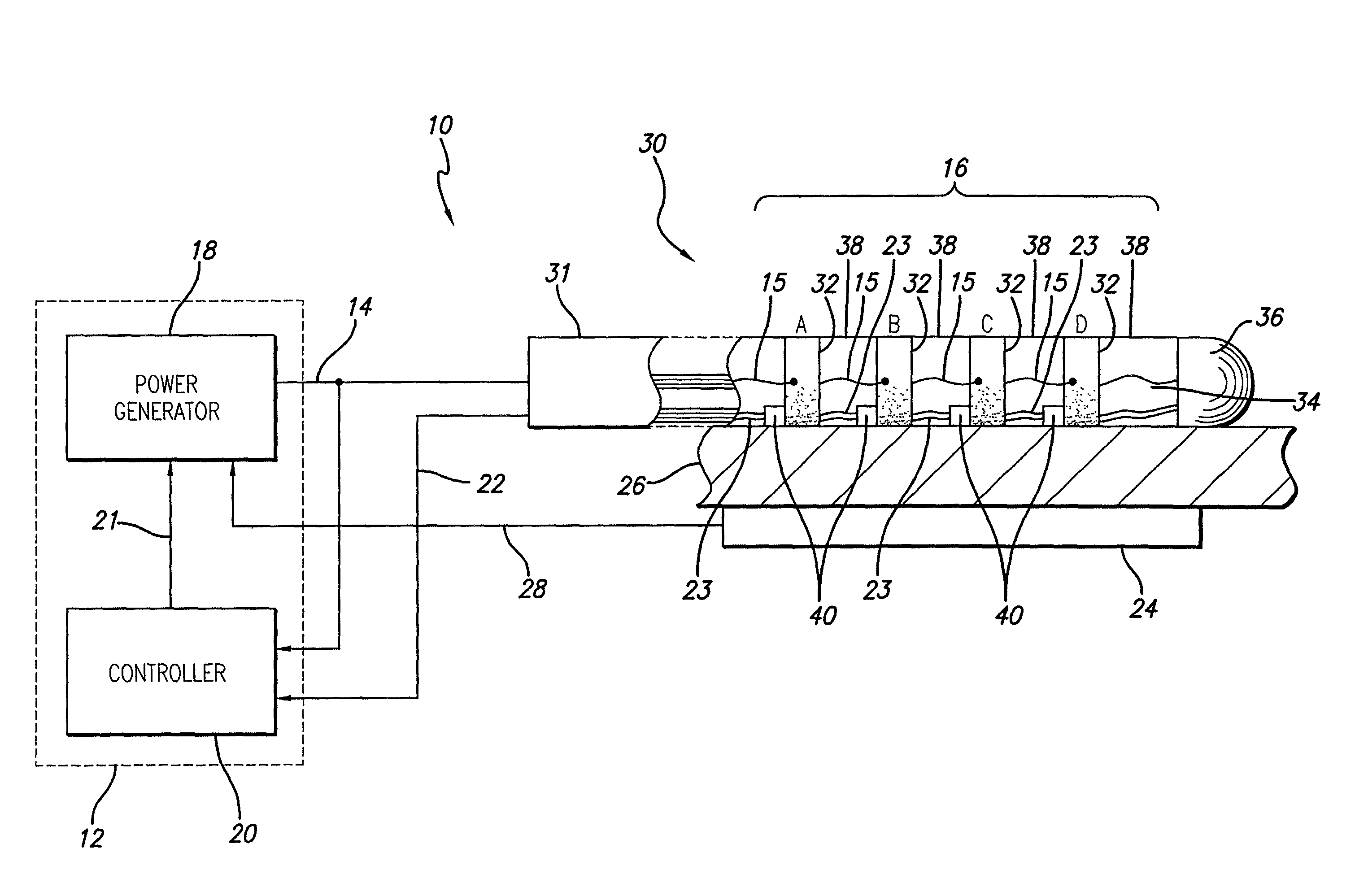
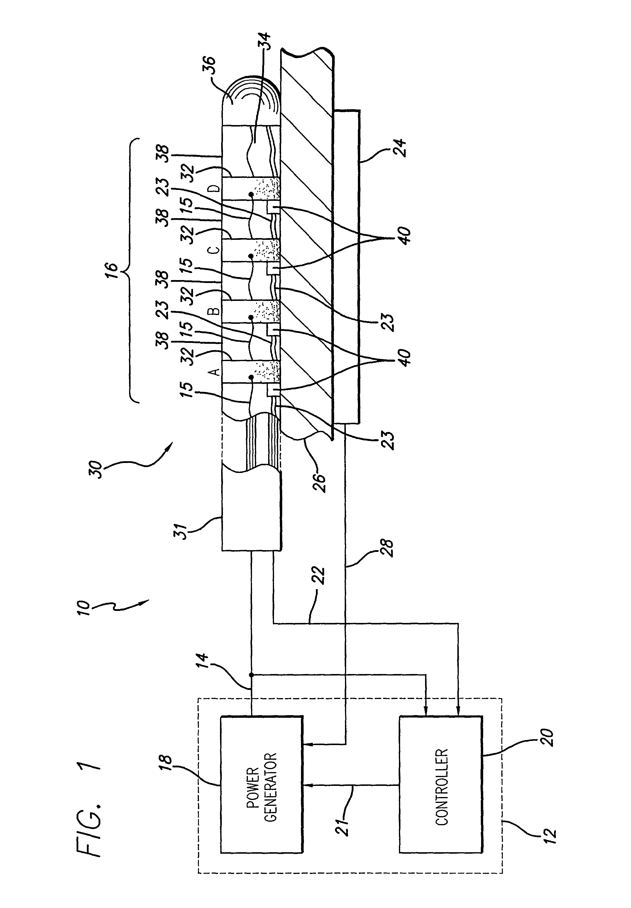
[0055] Turning now to the drawings, in which like reference numerals are used to designate like or corresponding elements among the several figures, in FIG. 1 there is shown an ablation apparatus 10 in accordance with aspects of the present invention. The apparatus 10 includes a power control system 12 that provides power or drive 14 to an electrode device 16. The power control system 12 comprises a power generator 18 that may have any number of output channels through which it provides the power 14. The operation of the power generator 18 is controlled by a controller 20 or processor which outputs control signals 21 to the power generator 18. The controller 20 monitors the power 14 provided by the power generator 18. In addition, the controller 20 also receives temperature signals 22 from the electrode device 16. Based on the power 14 and temperature signals 22 the controller 20 adjusts the operation of the power generator 18. A backplate 24 is located proximal to the biological si...


PUM


Abstract

A catheter carries a plurality of electrodes, each with multiple thermal sensors attached and is used to position the electrodes proximal biological tissue. A processor responsive to each of the thermal sensors determines the temperature at the thermal-sensor / electrode junction. A display provides a graphic representation of the temperatures of the thermal-sensor / electrode junctions. An exemplary representation is a bar graph having the temperature of one thermal sensor at one end and the temperature of another thermal sensor at the other end. The length of the bar graph combined with the position of the bar graph relative to a temperature range region provides an indication of the position of the thermal-sensor / electrode junctions relative to the biological tissue. The processor also monitors the spread between the sensor temperatures and compares it to a threshold value. Base on the result of the comparison, the processor controls the power applied to the electrode.

Description

BACKGROUND OF THE INVENTION[0001] The invention relates generally to an electrophysiological ("EP") apparatus and method for providing energy to biological tissue, and more particularly, to an ablation system having multiple-sensor electrodes and a controller for assessing the position of the electrode and the sensors relative to the biological tissue and the adequacy of the energy being applied.[0002] The heart beat in a healthy human is controlled by the sinoatrial node ("S-A node") located in the wall of the right atrium. The S-A node generates electrical signal potentials that are transmitted through pathways of conductive heart tissue in the atrium to the atrioventricular node ("A-V node") which in turn transmits the electrical signals throughout the ventricle by means of the His and Purkinje conductive tissues. Improper growth of, or damage to, the conductive tissue in the heart can interfere with the passage of regular electrical signals from the S-A and A-V nodes. Electrical...

Claims


Application Information

Patent Timeline
IPC IPC(8): A61B17/00A61B18/14
CPCA61B18/1492A61B2017/00101A61B2018/0016A61B2018/00702A61B2018/00791A61B2018/00797
Inventor SIMPSON, JOHN A.SHERMAN, MARSHALL L.WOOD, DAVID S.HALL, JEFFREY A.
Owner CARDIAC PACEMAKERS INC
Learn More