
Automatic gain control circuit for analog signals

Inactive Publication Date: 2002-09-12
IND TECH RES INST
View PDF0 Cites 5 Cited by
  • Summary
  • Abstract
  • Description
  • Claims
  • Application Information

AI Technical Summary

Benefits of technology

[0012] Accordingly, the purpose of the present invention is to provide an AGC circuit for analog signals, which produces gain-control signals S1 and S2 for controlling the gain of the signal amplification or attenuation, thereby automatically adjusting the amplification and attenuation of the input signals. In addition, the microprocessor selects one appropriate restoring parameters according to these gain-control signals to ensure that the result can conform to the input signal. When the AGC circuit of the present invention is applied to an analog-to-digital circuit, it can cooperate with the microprocessor to achieve the automatic gain switching function of the input analog signals by the microprocessor. In addition, in the conversion of the input signals, it can provide a quick response for the automatic adjustment of the gain.
[0016] The amplification / attenuation gain-adjusting circuit generates a gain-adjusting signal to control the gain value used in the amplifying / attenuation and automatically adjusts the amplification / attenuation of input signals quickly. The AGC circuit of the present invention is applied to an analog-to-digital circuit, it can cooperate with the microprocessor to achieve the automatic gain switching function of the input analog signals by the microprocessor. In addition, in the conversion of the input signals, it can provide a quick response for the automatic adjustment of the gain.

Problems solved by technology

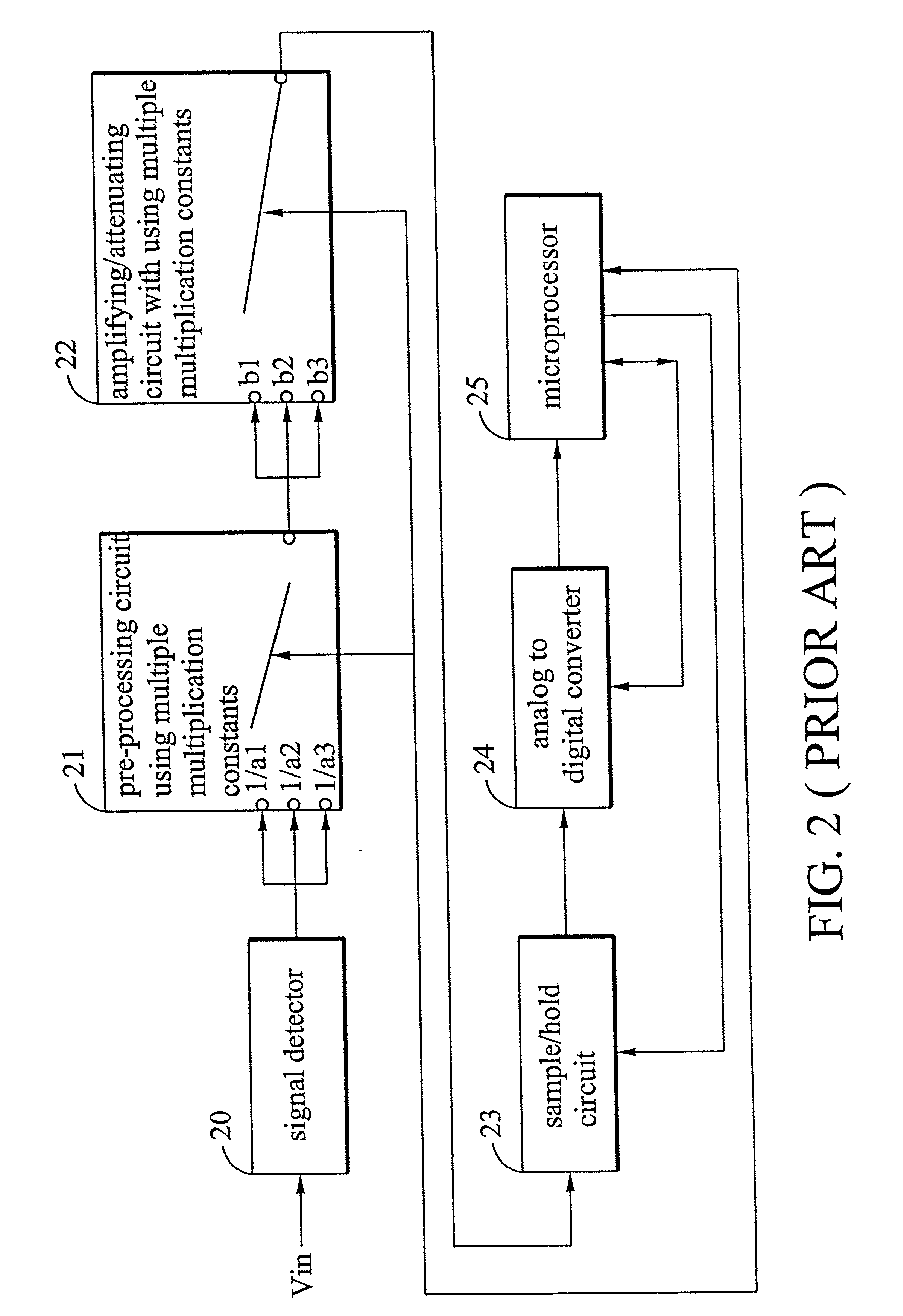
The second scheme cannot be widely applied in the industry since it requires manually changing the manual switch for changing the multiplication constants.
On the other hand, although the first scheme employs an automatic procedure for adjusting and changing multiplication constants, the microprocessor requires much time in each trial to find out the correct result.
Apparently, these two schemes are not suitable for the high-speed system.

Method used


Image

  • Automatic gain control circuit for analog signals
  • Automatic gain control circuit for analog signals
  • Automatic gain control circuit for analog signals

Examples


Embodiment Construction

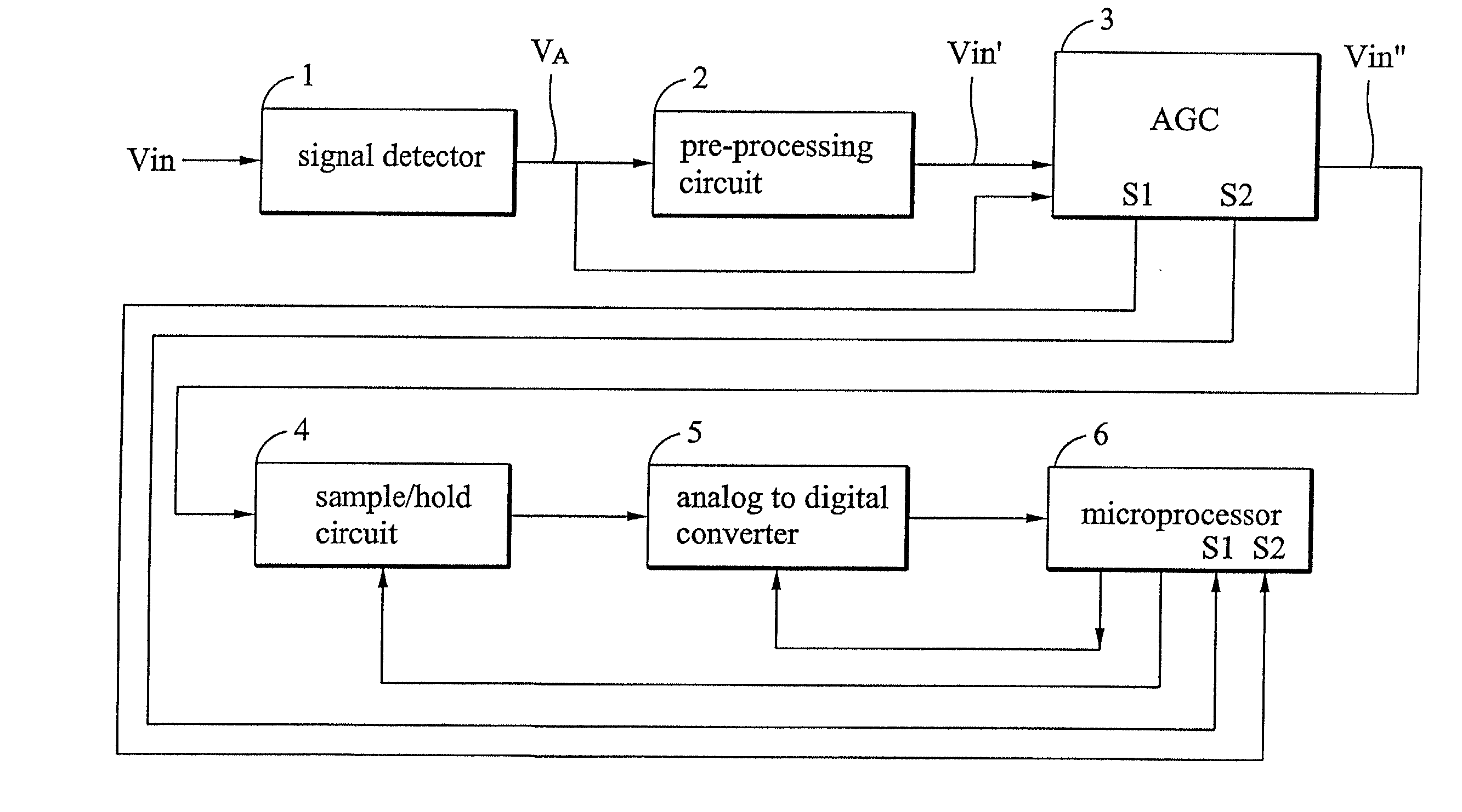
[0025] FIG. 4 is a block diagram of an analog-to-digital conversion circuit that comprises an AGC circuit in the embodiment of the present invention. The circuit shown in FIG. 4 includes a signal detector 1, a pre-processing circuit 2, an automatic gain control (AGC) circuit 3, a sample / hold circuit 4, an analog-to-digital converter 5 and a microprocessor 6. The AGC circuit disclosed in the present embodiment cooperates with the microprocessor 6 to quickly and automatically adjust the gain of the input analog signal.

[0026] FIG. 5 is a block diagram of illustrating the control function of the AGC circuit 3 shown in the FIG. 4. As shown in the figure, the AGC circuit 3 is composed of a buffer circuit 31, an amplifying / attenuating circuit 32, a gain-adjusting pre-processing circuit 33 and a amplification / attenuation gain-adjusting circuit 34.

[0027] After the signal detector 1 detects an analog input signal Vin, it produces an output signal VA. Then, the pre-processing circuit 2 attenua...


PUM


Abstract

A front-end signal-processing device having an automatic gain-control function used in the analog-to-digital conversion. The circuit comprises a buffer circuit, an amplifying / attenuating circuit, a pre-processing gain-adjusting circuit and an amplification / attenuation gain-adjusting circuit. In the front-end signal-processing device having an automatic gain-control function used in the analog-to-digital conversion, a set of gain-adjusting signals S1 and S2 are produced by hardware for controlling the amplification or attenuation gain of signals, thereby automatically adjusting the amplitude of the input signals. In addition, the microprocessor can select an appropriate restoring parameter according to the gain-adjusting signals to ensure that the numeral result conforms to the original input signal.

Description

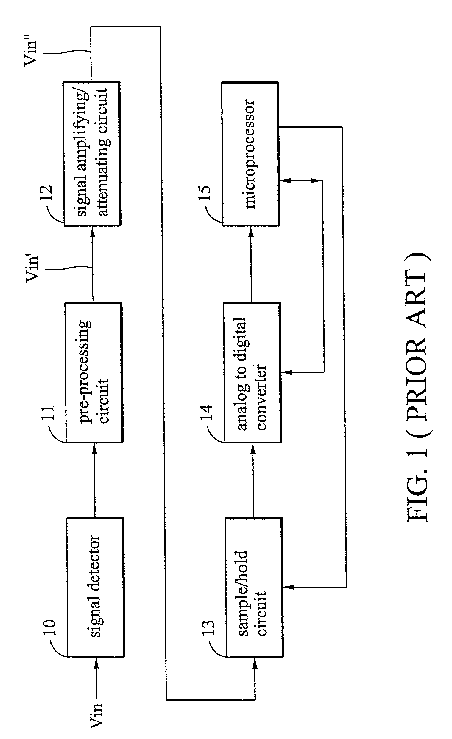
BACKGROUND OF THE INVENTION[0001] 1. Field of the Invention[0002] The present invention relates to a circuit for processing analog signals, and particularly to an automatic gain control circuit for analog signals.[0003] 2. Description of Related Art[0004] The analog-to-digital circuit is usually used in all kinds of equipment such as computers, gauges and industrial controlling apparatus. It can transform analog signals (ex. temperature, pressure etc.) to digital signals that are easily received and further processed by the digital processor.[0005] FIG. 1 (PRIOR ART) is a block diagram of a conventional analog-to-digital circuit with a single multiplication factor. The circuit comprises a signal detector 10, a pre-processing circuit 11, a signal amplifying / attenuating circuit 12, a sample / hold circuit 13, an analog-to-digital converter (ADC) 14 and a microprocessor 15. The signal detector 10 detects an analog input signal Vin. The pre-processing circuit 11 attenuates the analog inpu...

Claims


Application Information

Patent Timeline
IPC IPC(8): H03M1/18
CPCH03M1/186
Inventor LIN, SYH-SHOEIYOUNG, SANDRATSENG, WEN-LIANGCHANG, SENG-FA
Owner IND TECH RES INST
Learn More