
Gas cup seal for magneto-rheological damper

a magneto-rheological and fluid damper technology, applied in the field of magneto-rheological fluid dampers, can solve the problems of inability to accommodate the volume change, incompressible fluid in the damper, and other dampers change the internal volume, so as to achieve the effect of improving durability and service life, long and reliable service life, and increasing the average service life of the fluid damper

Inactive Publication Date: 2002-09-19
DELPHI TECH INC
View PDF0 Cites 22 Cited by
  • Summary
  • Abstract
  • Description
  • Claims
  • Application Information

AI Technical Summary

Benefits of technology

[0009] The present invention provides a dynamic seal for a gas cup of an MR fluid damper that has a substantially improved durability and service life. With the present invention, the average service life of the gas cup dynamic seal is more comparable to the average service life of other components in the MR fluid damper, and thus, the average service life of the MR fluid damper is thus substantially increased. Therefore, an MR fluid damper employing the gas cup seal of the present invention is especially useful in vehicle suspension systems where a long and reliable service life is at a premium. The dynamic seal of the present invention is achieved using known, inexpensive O-rings; and thus, the dynamic seal of the present invention does not increase the manufacturing costs of the MR fluid damper.
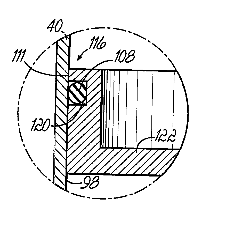
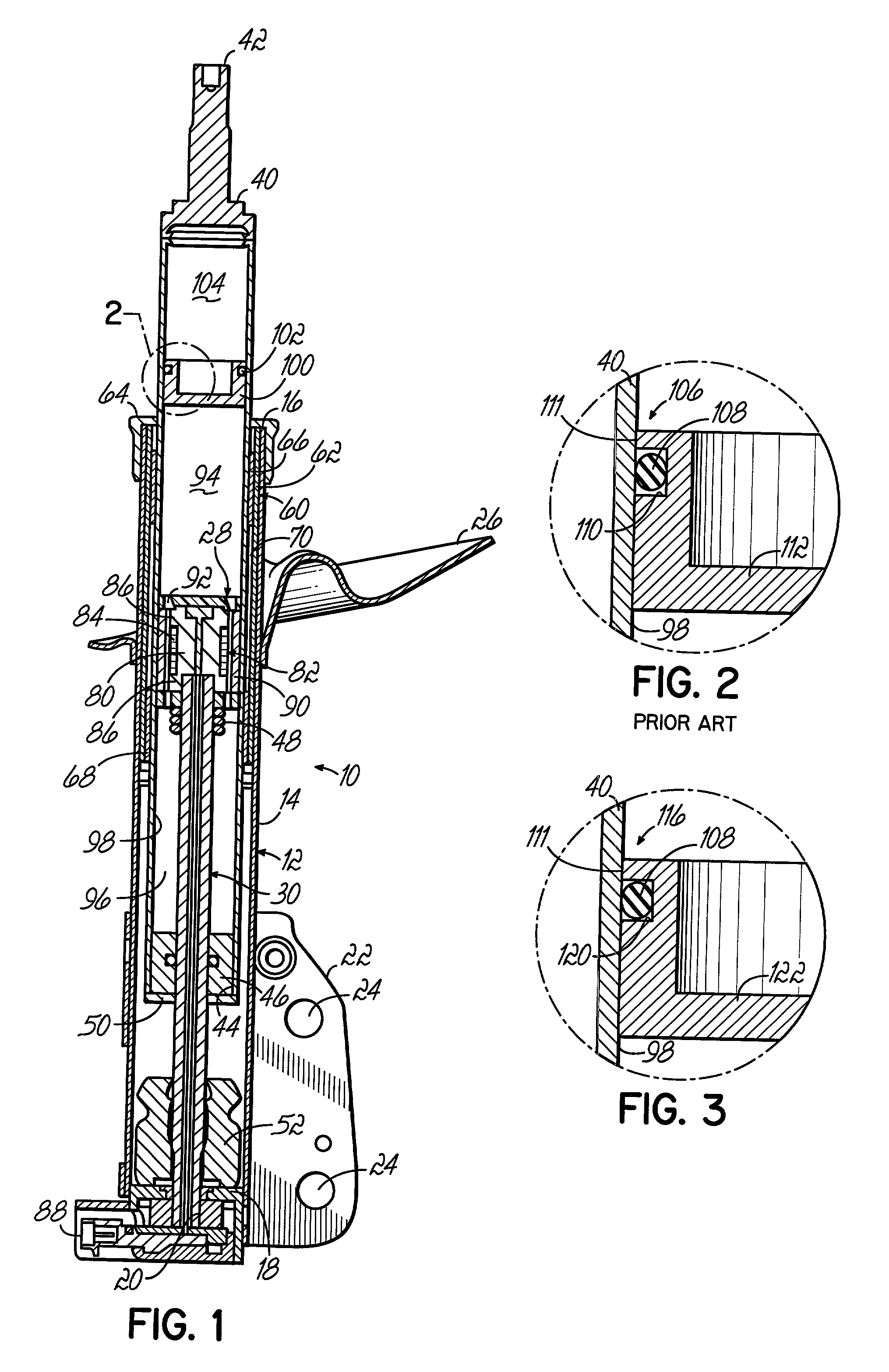
[0010] According to the principles of the present invention and in accordance with the described embodiment, the present invention provides a magneto-rheological ("MR") damper having a closed damper body tube. A gas cup slidably moves within the damper body tube and isolates an MR fluid from a gas in one end of the damper body tube. A dynamic seal is formed in an outer surface of the gas cup and is in sealing contact with an inner surface of the damper body tube. The dynamic seal comprises an MR fluid compatible O-ring located in a narrow O-ring groove disposed in the outer surface of the gas cup. The narrow O-ring groove is sized to reduce entrapment of abrasive magnetic particles in the MR fluid between the O-ring and the inner surface of the damper body tube.

Problems solved by technology

Second, other dampers change internal volume even with a monotube cylinder of fixed length.
The fluid in the damper, being incompressible, is not capable of accommodating these volume changes.
However, the service life of O-rings is shorter than desired.
The magnetic particles in the MR fluid are abrasive, tending to prematurely wear the O-ring, and leakage past the gas cup O-ring due to premature wear leads to a premature failure of the MR fluid damper.

Method used


Image

  • Gas cup seal for magneto-rheological damper
  • Gas cup seal for magneto-rheological damper

Examples


Embodiment Construction

[0017] FIG. 1 illustrates a linearly-acting magneto-rheological (MR) fluid damper and in particular, a monotube gas-charged suspension strut 10. In general, the strut 10 is designed for operation as a load-bearing and shock-absorbing device within a vehicle suspension system and is connected between the sprung (body) and unsprung (wheel assembly) masses (not shown). The strut 10 comprises a housing 12 that includes a housing tube 14 with an open end 16 and a closed end 18. The closed end 18 includes an opening 20. A mounting bracket 22 near closed end 18 is secured in position by a suitable means such as welding. The mounting bracket 22 has suitable openings 24 for connection to the unsprung mass of the vehicle at a location such as the steering knuckle (not illustrated). A spring seat 26 is also received on the housing tube 14 and is positioned as required by the particular application within which the strut 10 will operate. The spring seat 26 is fixed in position on the housing tu...


PUM


Abstract

A magneto-rheological ("MR") damper having a gas cup that slidably moves within a damper body tube and isolates an MR fluid from a gas in one end of the damper body tube. The gas cup has a dynamic seal that comprises an MR fluid compatible O-ring located in a narrow O-ring groove disposed in an outer surface of the gas cup. The narrow O-ring groove is sized to reduce entrapment of abrasive magnetic particles in the MR fluid between the O-ring and an inner surface of the damper body tube. The O-ring groove has a free roll room of about less than 12%.

Description

FIELD OF THE INVENTION[0001] The present invention relates to a magneto-rheological (MR) fluid damper, and more particularly, to a linearly-acting MR fluid damper suitable for vibration damping in a vehicle suspension system.BACKGROUND OF THE INVENTION[0002] Magneto-rheological (MR) fluids are materials that respond to an applied magnetic field with a change in rheological behavior (i.e., change in formation and material flow characteristics). The flow characteristics of these MR fluids change several orders of magnitude within milliseconds when subjected to a suitable magnetic field. In particular, magnetic particles noncolloidally suspended in fluid align in chain-like structures parallel to the applied magnetic field increasing the viscous characteristics of the MR fluid.[0003] Devices such as controllable dampers benefit from the controllable viscosity of MR fluid. For example, linearly-acting MR fluid dampers are used in vehicle suspension systems as vibration dampers. At low l...

Claims


Application Information

Patent Timeline
IPC IPC(8): F16F9/06F16F9/36F16F9/53
CPCF16F9/067F16F9/36F16F9/535
Inventor HOPKINS, PATRICK NEILROBINSON, FRANK M.HURTT, MICHAEL W.KRUCKEMEYER, WILLIAM CHARLESOLIVER, MICHAEL L.
Owner DELPHI TECH INC
Learn More