
Interface apparatus provided between two remote control systems having different transmission modes

a technology of remote control system and interface apparatus, which is applied in the direction of process and machine control, electrical programme control, program control, etc., can solve the problems of complex connection relationship and output result representing abnormality

Inactive Publication Date: 2002-10-03
MATSUSHITA ELECTRIC WORKS LTD
View PDF7 Cites 5 Cited by
  • Summary
  • Abstract
  • Description
  • Claims
  • Application Information

AI Technical Summary

Benefits of technology

[0011] Another object of the present invention is to provide an inter-system interface apparatus between a polling communication system and a contention communication system, capable of controlling and monitoring a load of a counterpart system by setting simple connection relationship even though the number of combinations of inputs and loads increases.
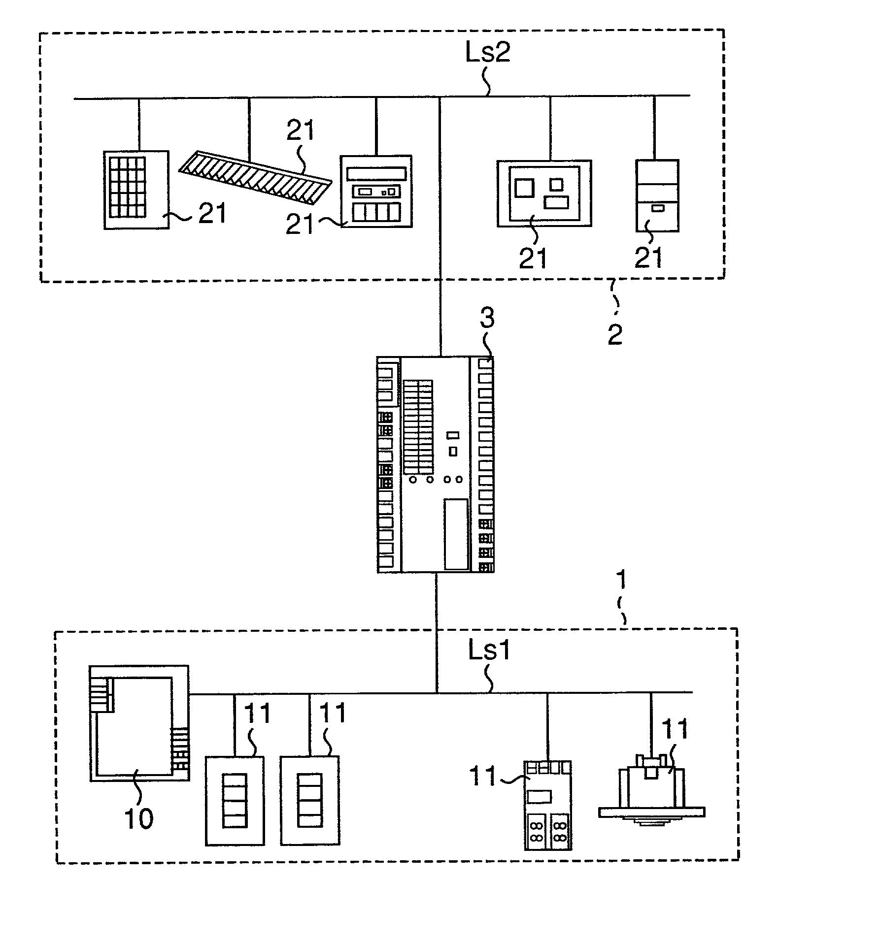
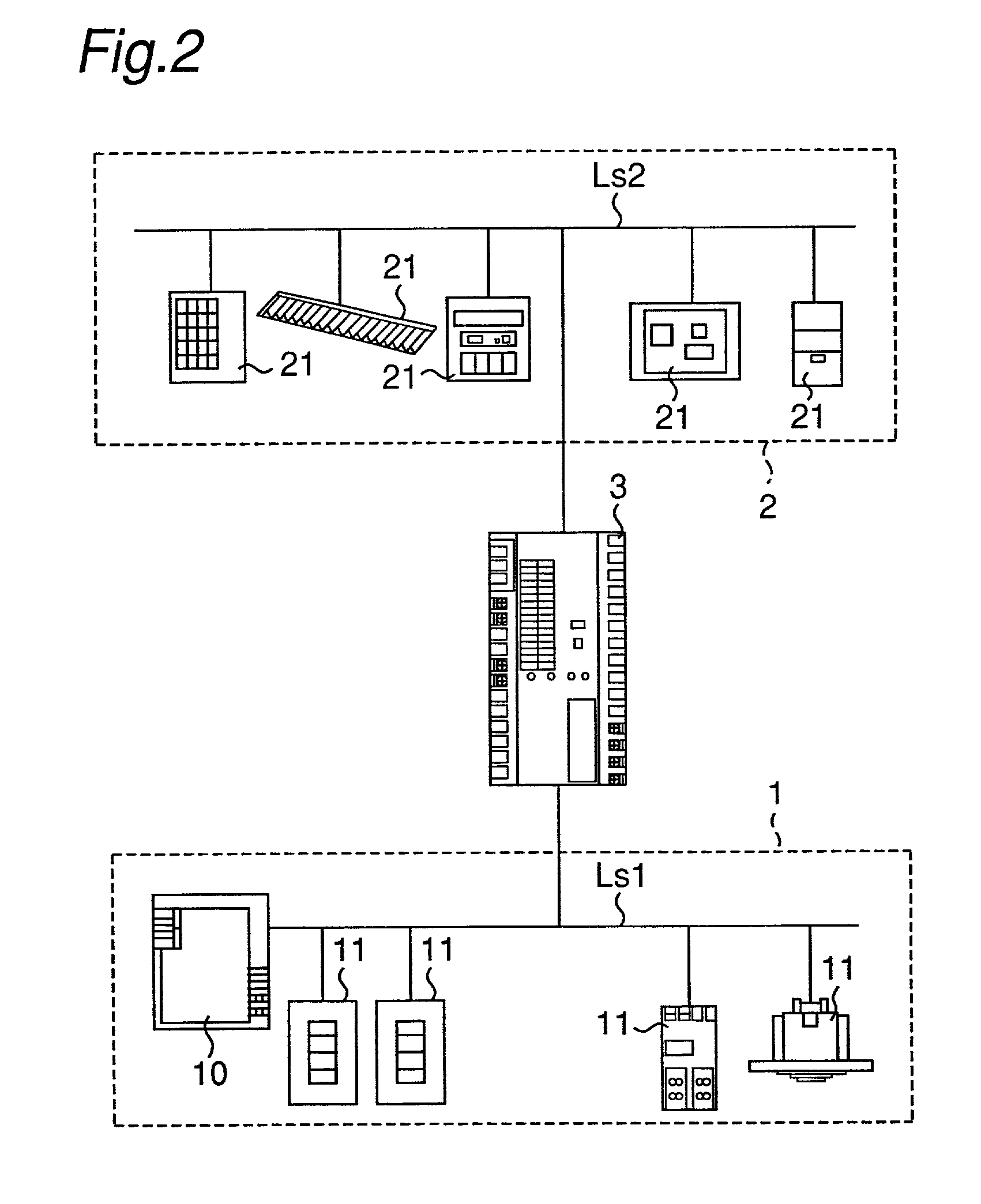
[0021] According to the present invention, the interface apparatus allows mapping of one input to another load unit or makes correspondence between the first remote control system and the second remote control system. In addition to this, the interface apparatus can function equivalently as a plurality of terminal units for the first remote control system, and can function equivalently as a plurality of node units for the second remote control system. This leads to controlling a plurality of load units in response to a plurality of inputs by connecting the terminal units to the first signal line, connecting the node units to the second signal line, and setting simple connection relationship.
[0022] When the control section executes only one processing out of the above-mentioned two processings, the interface apparatus provides only one function, and it is make the whole system easily.
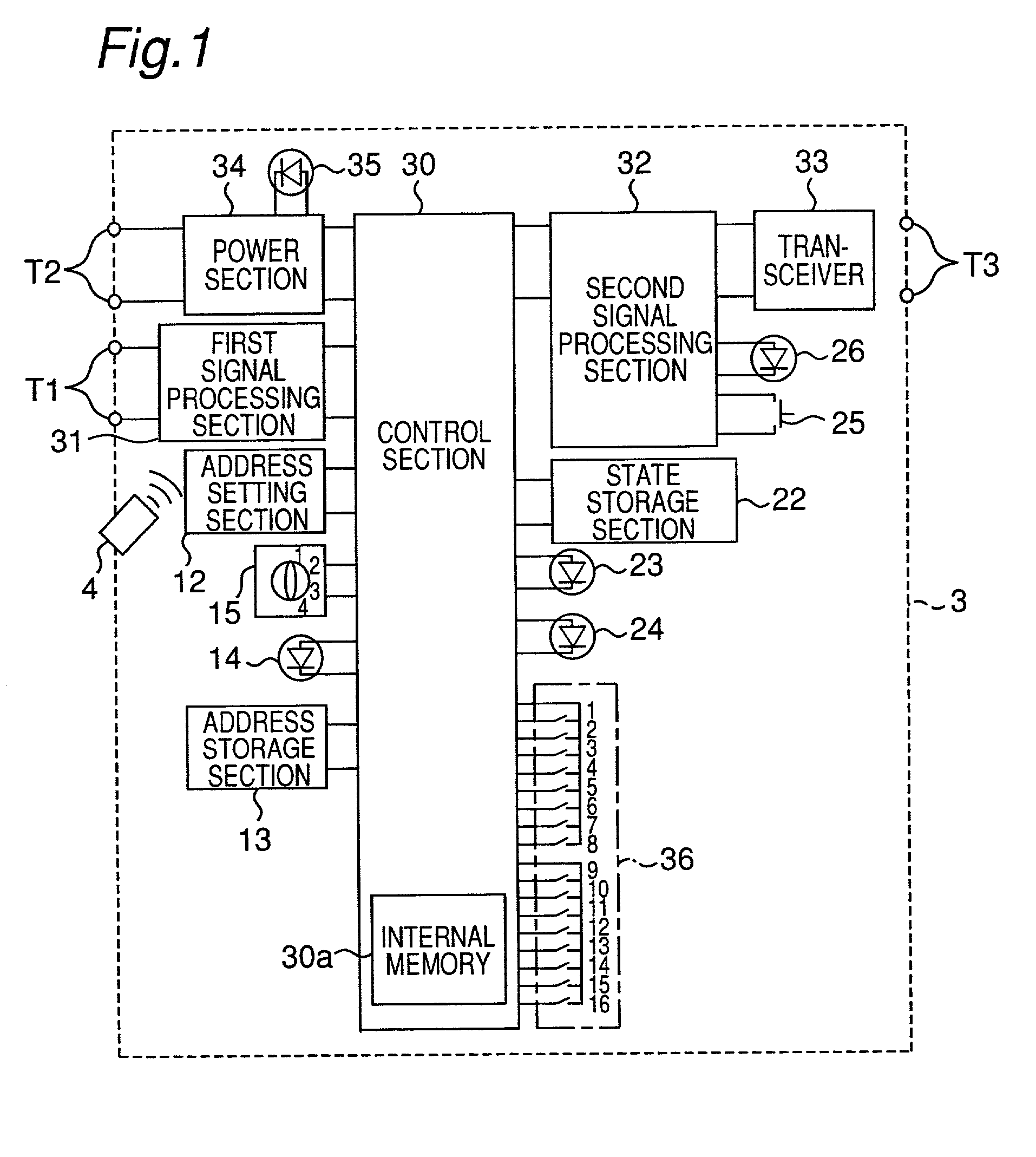
[0024] When the information storage section stores mapping information for mapping the respective equivalent addresses stored in the address storage section to the addresses stored in the state storage section, in one to one correspondence. This leads to that the correspondence relationship between the node units and the terminal units can be easily understood, and the load units can be easily controlled.
[0025] When the information storage section stores mapping information for mapping the respective equivalent addresses stored in the address storage section to the addresses stored in the state storage section, in one to plural N correspondence. This leads to that a plurality of node units of the second remote control system can be easily batch-controlled by one terminal unit of the first remote control system.
[0027] When the control section further includes the second switch for selecting one logical operation from OR, AND, NOR, and NAND logical operations to be performed for a plurality of N transmission signals which represent results of operating states of a plurality of N second load units to be controlled and which are received by the second signal processing section, and the control section performs the logical operation selected by the second switch for a plurality of N transmission signals which represents results of operating states of a plurality of N second load units to be controlled and which is received by the second signal processing section, and transmits a transmission signal representing the results of the logical operation to the first terminal unit mapped to the plurality of N second load units. This allows collective management of predetermined operating states of a plurality of second load units in the first remote control system, and it is possible to monitor checking any second load units which the user has forgot to turn off, and to monitor an abnormal state of the second load units. Providing the second switch for batch-control over the second load units corresponding to this kind of monitoring results allows such a control as collectively turning off the second load units when the user has forgot to turn off the second load units.

Problems solved by technology

As a result, there will occur such a problem that the connection relationship becomes complicated.
Therefore, since the result of the operation of an ON state is outputted when all the units controlled in the contention communication system 2 are stopped, the outputted result represents occurrence of abnormality.

Method used


Image

  • Interface apparatus provided between two remote control systems having different transmission modes
  • Interface apparatus provided between two remote control systems having different transmission modes
  • Interface apparatus provided between two remote control systems having different transmission modes

Examples


Embodiment Construction

s

[0100] According to the preferred embodiments of the present invention, the inter-system interface apparatus 3 allows mapping of one input to another load unit or makes correspondence between the polling communication system 1 and the contention communication system 2. In addition to this, the inter-system interface apparatus 3 can function equivalently as a plurality of terminal units 11 for the polling communication system 1, and can function equivalently as a plurality of node units 21 for the contention communication system 2. This leads to controlling a plurality of load units in response to a plurality of inputs by connecting the terminal units 11 to the signal line Ls1, connecting the node units 21 to the signal line Ls2, and setting simple connection relationship.

[0101] When the control section 30 executes only one processing out of the above-mentioned two processings, the interface apparatus provides only one function, and it is make the whole system easily.

[0102] When the...


PUM


Abstract

In an interface apparatus provided between a first remote control system of polling communication system and a second remote control system of contention communication system, a control section executes at least one processing of the following processings based on mapping information of addresses. A first control processing is to transmit a transmission signal for controlling a second load unit to a second node unit responsive to a transmission signal which represents reception of a first input signal and is transmitted from a first terminal unit, thereby controlling the second load unit based on the first input signal. A second control processing is to transmit a transmission signal for controlling a first load unit to the first load unit responsive to a transmission signal which represents reception of the second input signal and is transmitted from the second node unit, thereby controlling the first load unit based on the second input signal.

Description

[0001] 1. Field of the Invention[0002] The present invention relates to an interface apparatus between two remote control systems having transmission modes different from each other, and in particular, an interface apparatus between a first remote control system of polling communication system and a second remote control system of convention system.[0003] 2. Description of the Related Art[0004] Conventionally, there has been proposed a remote control system of polling system (hereinafter referred to as a "polling communication system") in which a plurality of terminal units and one transmission unit are connected with each other via a signal line, and the transmission unit performs data exchange or data of transmission and receipt between the terminal units by accessing respective terminal units by using respective addresses allocated to respective terminal units by the time division multiplexing access. In such a remote control system, in order to control an action of a load in res...

Claims


Application Information

Patent Timeline
Patent Type & Authority Applications(United States)
IPC IPC(8): H04L12/403H04L12/46H04Q9/00H05B37/02
CPCH04L12/4625H04L12/403H04Q9/00
Inventor HATEMATA, TAKESHI
Owner MATSUSHITA ELECTRIC WORKS LTD
Learn More